P&ID Symbol Legend
Piping & Instrumentation Diagram (P&ID) is a schematic representation illustrating the functional relationships between piping, instrumentation, and system equipment components within automation and process control systems. These diagrams are primarily created and utilized by engineers designing manufacturing processes for physical plants.
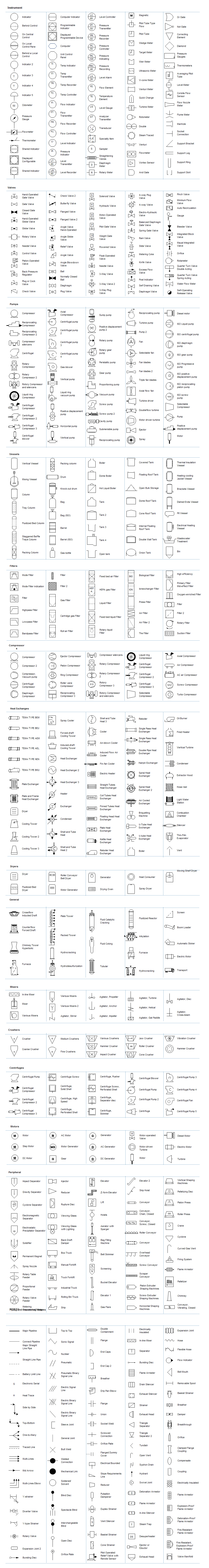
Our detailed Piping and Instrumentation Diagram documentation provides a comprehensive library of standardized shapes & symbols for creating precise P&IDs and PFDs. This includes specialized symbols for instruments, valves, pumps, heat exchangers, mixers, crushers, vessels, compressors, filters, motors, and connection points.
Standard P&ID Symbols
P&ID components are represented by standardized symbols that are not drawn to scale. These symbols are always labeled with descriptive words, letters, and numbers for precise component identification. It's important to note these diagrams do not represent physical locations or component proximity. Their primary purpose is to illustrate process flow and functional relationships rather than serve as physical layout maps.
Download Free P&ID Symbol Legend PDF
Download Free P&ID Software with Editable Symbols
Where to Find All P&ID Symbols
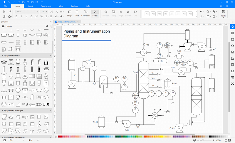
EdrawMax provides access to an extensive library of P&ID symbols and professional templates. Our intuitive diagramming tool features a drag-and-drop interface with preset drawing symbols that simplify P&ID creation. You can locate all pre-designed P&ID symbols under the Industrial Automation & PID category in the EdrawMax library.
EdrawMax
All-in-One Diagram Software
- Superior file compatibility: Import and export drawings to various file formats, such as Visio
- Cross-platform supported (Windows, Mac, Linux, Web)


When you enter the EdrawMax workspace, the symbol library appears on the left side of the canvas. All pre-designed P&ID symbols are organized under the Industrial Automation and P&ID categories, ready to represent functional relationships between piping, instrumentation, and system equipment.
How to Create a P&ID Diagram Using Standard Symbols
Watch the video below to learn how to use P&ID symbols and create professional diagrams with EdrawMax.
Professional Tips for Creating P&ID Diagrams
Follow these essential steps when creating a P&ID with professional software:
1. Develop and finalize your equipment list, then use the symbol library to represent each component accurately.
2. Connect pipes and equipment systematically, then thoroughly review all connections. Collaborate with colleagues to identify and correct any imperfections.
3. Share your completed diagram with team members and stakeholders for feedback and approval.
Related Resources
5 Best P&ID Software Solutions


