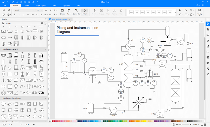
What is a Piping and Instrumentation Diagram (P&ID)
Master P&ID Creation with Professional Tools
EdrawMax is the ultimate diagramming solution for engineers and designers. Discover everything about P&ID diagrams - from fundamental symbols to advanced templates - and learn how to create professional-grade diagrams efficiently. Start your free trial today!
Part 1: Understanding P&ID Diagrams
A Piping and Instrumentation Diagram (P&ID) visually represents the components of industrial process systems - including equipment, valves, reducers, and other elements - commonly used in engineering projects like steam boiler installations, heat exchanger setups, and electric boiler configurations.
To effectively interpret a P&ID, begin by analyzing smaller sections before examining the complete system. Trace pipelines from individual equipment pieces to understand the sequential flow of the entire process.
Primary applications of piping and instrumentation diagrams include:
- Comprehending engineering project design specifications;
- Facilitating efficient system operation, maintenance, and modification;
- Demonstrating system sequences with emphasis on control schemes, safety protocols, regulatory compliance, and operational procedures.
Part 2: Evolution of Piping and Instrumentation Diagrams
Piping and Instrumentation Diagrams serve as crucial planning documents for process flows, guiding installers during plant setup. These diagrams are preceded by Process Flow Diagrams (PFDs), which outline conceptual workflows without detailed measurements or specifications.
While PFDs establish the theoretical framework for equipment functionality, P&IDs provide implementation specifics including piping systems, motors, and critical components. However, P&IDs should maintain focus on major elements rather than exhaustive detail - specialized diagrams should be created for complex sections requiring additional clarification.
Part 3: Benefits and Limitations of P&IDs
Piping and Instrumentation Diagrams offer distinct advantages and challenges that vary by project requirements. Key considerations include:
Advantages
- Enables accurate construction process evaluation
- Provides foundation for control system programming
- Serves as universal engineering language for global collaboration
- Facilitates development of safety control systems
Limitations
- Lacks complete reliability due to absence of precise measurements
- Requires Process Flow Diagram reference for independent creation
- Project-specific customization needed for each implementation
- Demands strict symbol adherence to prevent equipment design errors
P&IDs find applications across industries including metallurgy, HVAC, and power generation, with primary uses being:
- Designing complex manufacturing processes with critical safety considerations
- Training personnel and contractors for plant operations
- Developing project specifications and cost estimates
Part 4: Essential P&ID Symbols
While P&ID formats vary, they typically include these core elements:
- Equipment components (valves, reducers, drains, etc.)
- Technical specifications (sizes, tag numbers, capacity ratings)
- System details (identification markers, insulation requirements, flow directions)
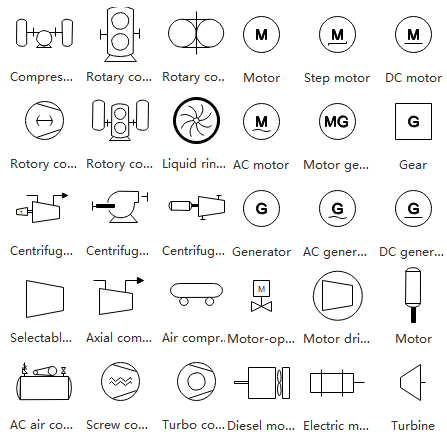
Equipment Symbols
This category encompasses specialized industrial components including compressors, conveyors, motors, turbines, and vacuum systems.
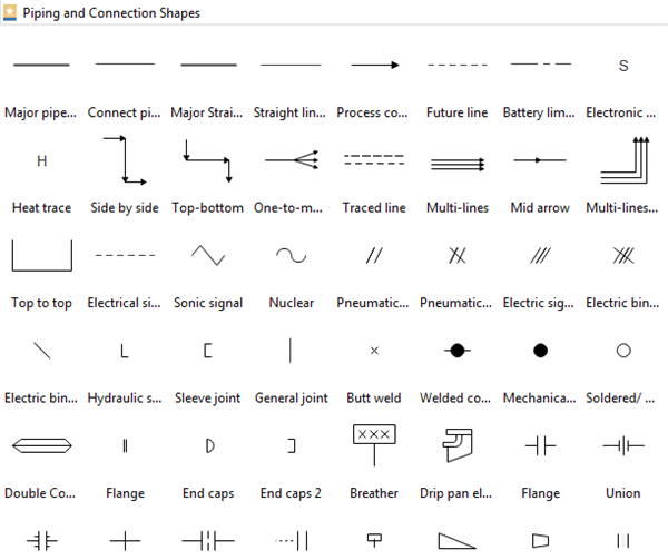
Piping and Connection Symbols
These symbols represent fluid transport systems constructed from various materials, featuring multi-line pipes, separators, and specialized connections.
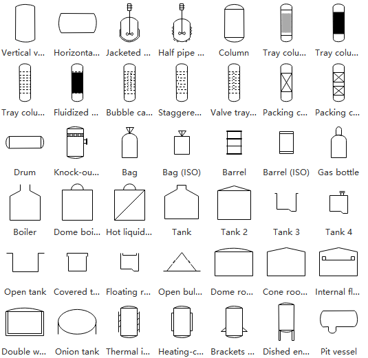
Vessel Symbols
Representing fluid containers that modify or store materials, this category includes tanks, columns, and specialized containment systems.
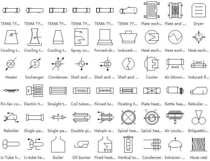
Heat Exchanger Symbols
These symbols depict thermal transfer devices including boilers, condensers, and specialized heat exchange equipment.
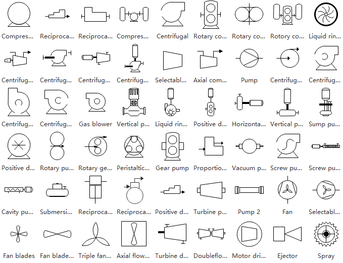
Pump Symbols
Representing pressure-based fluid movement systems, this category includes pumps, fans, ejectors, and spray mechanisms.
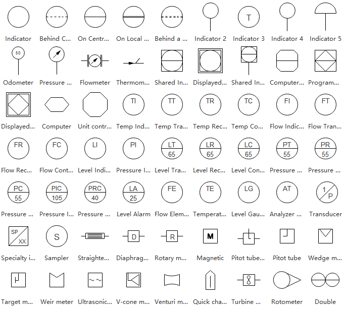
Instrument Symbols
These symbols depict measurement and control devices for parameters like flow, temperature, and pressure.
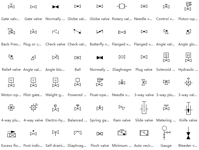
Valve Symbols
Representing flow control mechanisms, this section includes rotameters, gauges, ball valves, and specialized control valves.
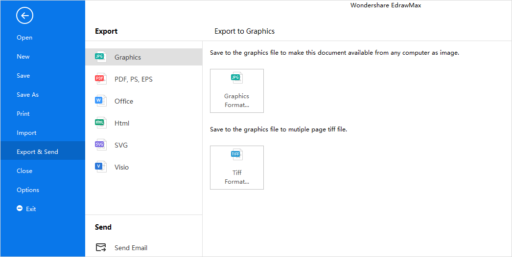
Part 5: Step-by-Step P&ID Creation


Step 1: Launch EdrawMax and navigate to [Industrial Engineering] to access P&ID templates.
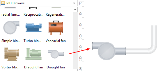
Step 2: Drag and drop pre-built symbols from the extensive library or utilize templates for accelerated workflow.
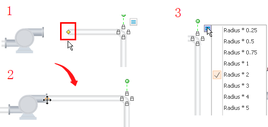
Step 3: Connect equipment with properly oriented pipelines, adjusting dimensions to meet project specifications.
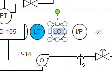
Step 4: Customize components by modifying colors, sizes, and adding descriptive labels.
Step 5: Export completed diagrams to multiple formats (JPG, PNG, SVG, PDF, Office formats) for seamless sharing.
Discover why professionals choose EdrawMax for their diagramming needs - intuitive for beginners yet powerful enough for experts.
Part 6: Professional P&ID Design Tips
Optimize your P&ID creation process with these professional recommendations:
- Include critical components: essential valves, mechanical equipment, flow directions, and control inputs
- Avoid excessive detail - create separate diagrams for complex subsystems
- Develop comprehensive equipment lists before diagramming
- Conduct thorough pipeline connectivity checks and system simulations
- Incorporate feedback from experienced engineers
Part 7: Ready-to-Use P&ID Templates
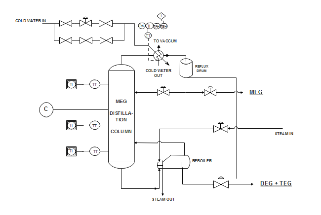
Water Boiling Process
This template demonstrates phase change from liquid to gas, occurring when vapor pressure equals atmospheric pressure.
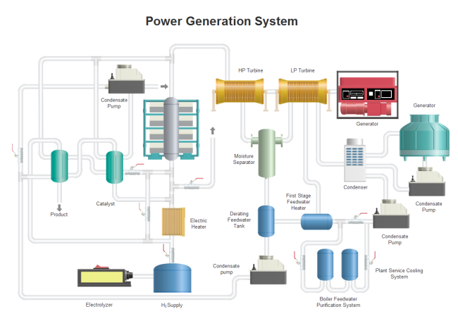
Power Generation System
This comprehensive template illustrates electricity generation infrastructure, featuring power supply tanks and LP turbines in an industrial configuration.
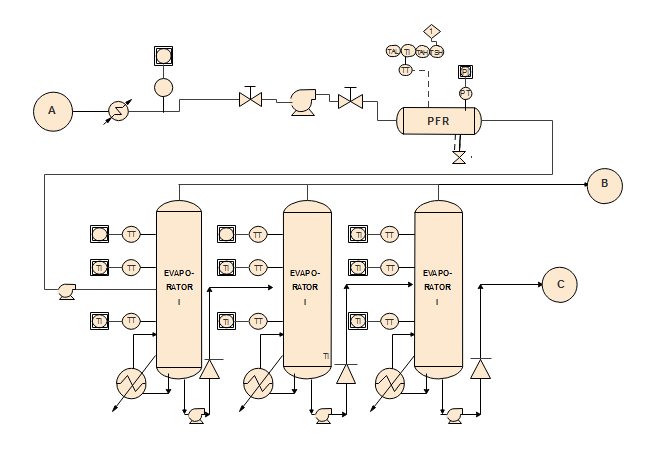
Evaporation Process
This detailed diagram presents an evaporation system with three primary evaporators, clearly demonstrating water transformation processes through pipeline analysis.
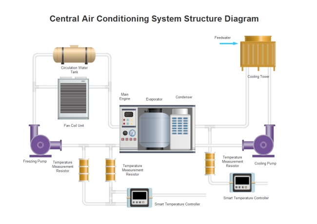
Air Conditioning System
This P&ID template illustrates HVAC processes for environmental control, featuring a central air conditioner with multi-directional piping for heat and moisture removal.
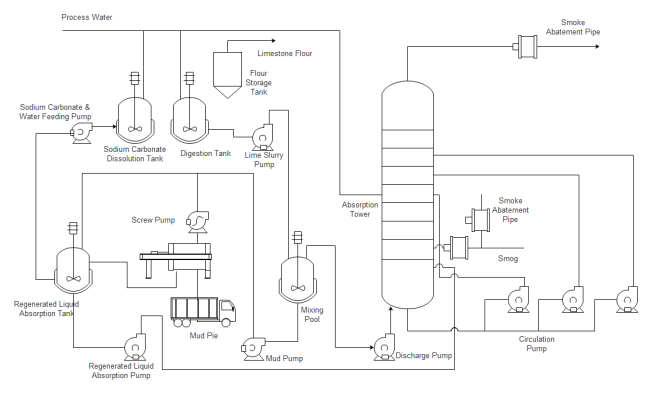
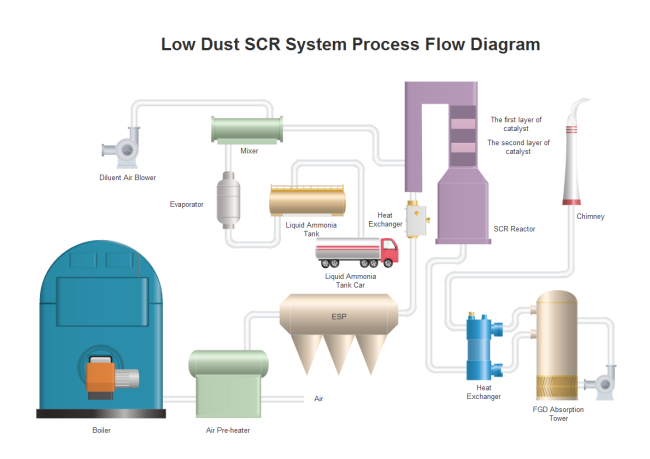
Low Dust SCR System
This diagram showcases a Selective Catalytic Reduction system for advanced emissions control in industrial applications.
Part 8: Key Takeaways
Piping and Instrumentation Diagrams serve as fundamental tools for industrial equipment design and implementation. These technical drawings build upon Process Flow Diagrams to provide practical guidance for engineers during system installation.
Since P&IDs focus on major system components rather than minute details, supplementary diagrams may be necessary to document specialized subsystems and precise component specifications.
Additional Templates
Explore these editable P&ID templates to enhance your understanding of industrial diagramming. All templates are compatible with our free diagramming software.
 |
 |
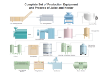 |
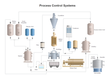
| Factory System | Process Control System | Juice Processing System |
 |
 |
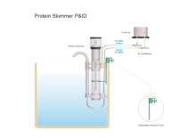 |
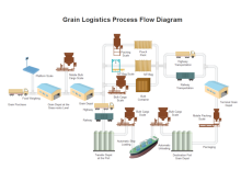
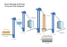
| Grain Logistics System | Grain Storage System | Protein Skimmer System |
Related Resources


