Process Flow Diagram Symbols and Their Usage
Ready to Create Your Process Flow Diagram?
EdrawMax specializes in professional diagramming and visualization. This comprehensive guide shows you how to create process flow diagrams quickly and efficiently. Get started with our free trial today!
Process flow diagrams utilize specialized shapes to represent different types of equipment, valves, instruments, and piping systems. This comprehensive guide provides all the essential process flow diagram symbols and demonstrates how to create professional process flow diagrams efficiently and accurately.
EdrawMax includes standardized symbols for mechanical equipment, piping systems, valves, equipment drivers, instrumentation, and control systems. These PFD symbols are strategically arranged to clearly define process flow diagrams. With EdrawMax's extensive library of pre-made PFD symbols, you can create professional process flow diagrams in minutes!
Contents
- What is a Process Flow Diagram?
- Process Flow Diagram Symbols - Equipment
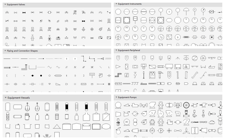
- Process Flow Diagram Symbols - Valves
- Process Flow Diagram Symbols - Piping Lines
- Process Flow Diagram Symbols - Instruments
- Process Flow Diagram Symbols - Centrifuges
- Process Flow Diagram Symbols - Heat Exchangers
- Process Flow Diagram Symbols - Crushers
- Use EdrawMax for Process Flow Diagram Creation
What is a Process Flow Diagram?
The Process Flow Diagram is a graphical representation used to illustrate key components of industrial processes in manufacturing plants. It is widely utilized in chemical, petroleum, and process engineering industries.
Process flow diagrams serve multiple purposes: understanding process sequences, modeling workflows, documenting procedures, ensuring quality control standards, and improving operational efficiency. These diagrams map entire processes from start to finish, illustrating how equipment and chemicals interact within industrial facilities. They provide visual documentation of processes, including all tasks and steps in their proper sequence.
What's Included in a Process Flow Diagram?
A comprehensive process flow diagram typically includes:
- Equipment representations
- Valve symbols
- Piping line notations
- Instrumentation symbols
- Centrifuge illustrations
- Heat exchange components
- Crusher symbols
The following sections provide detailed introductions to these symbols with visual examples to facilitate understanding.
EdrawMax
All-in-One Diagram Software
- Superior file compatibility: Import and export drawings to various file formats, such as Visio
- Cross-platform supported (Windows, Mac, Linux, Web)


Process Flow Diagram Symbols - Equipment
Pumps and tanks are available in various designs and configurations to meet different industrial requirements.
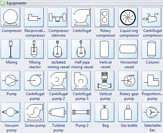
A compressor is a mechanical device that intakes a medium and compresses it to reduce volume. Typically, a mechanical or electrical drive powers the pump that compresses the medium.
A pump is a mechanical apparatus that uses suction or pressure to move liquids, compress gases, or force air into inflatable objects. Pump symbols often resemble those used for compressors in technical diagrams.
Mixing equipment combines multiple materials to form a homogeneous substance or mixture.
A mixing vessel is a specialized container designed to blend various components efficiently.
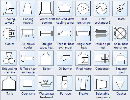
The heat exchanger facilitates thermal energy transfer between two process flows through conductive and convective heat transfer mechanisms.
Cooling towers dissipate heat energy to the atmosphere through water evaporation processes.
The cooler is a device or system that reduces air temperature through water evaporation or maintains cool temperatures.
A furnace is equipment designed to heat continuous air currents through internal combustion without mixing fresh air with combustion byproducts.
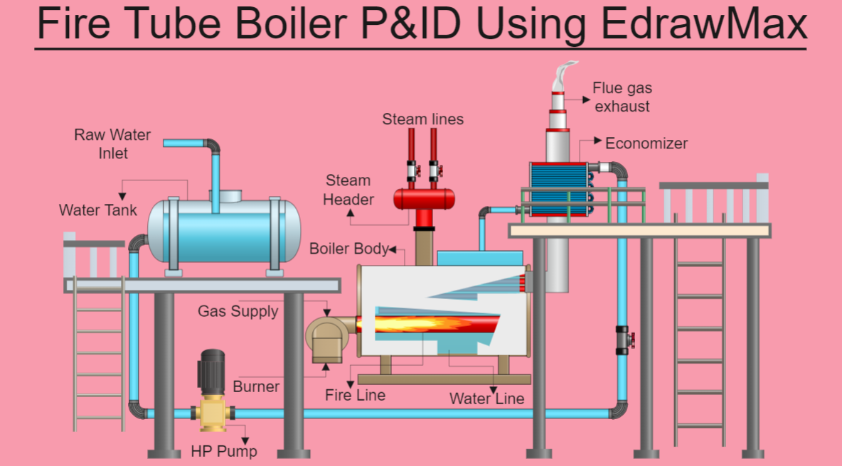
The boiler is a pressurized vessel where water or other fluids are heated to generate steam or hot water.
The tank stores various process fluids under different operational conditions and pressures.
Process Flow Diagram Symbols - Valves
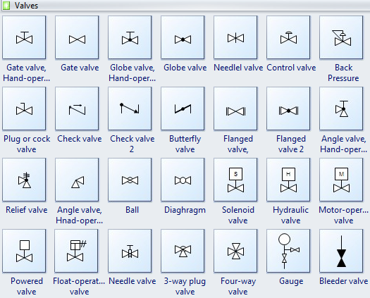
A gate valve controls the flow of liquids and gases through pipeline systems.
A check valve, also known as a one-way valve, prevents backflow in piping systems.
A Globe valve regulates or stops fluid flow through piping networks.
A ball valve features a spherical disc that controls flow through rotational operation.
A butterfly valve installs between flanges using separate bolt sets for each connection point.
An angle valve is oriented at a 90-degree angle relative to gate valve configurations.
A needle valve utilizes a slender, tapered point on the valve stem to precisely restrict or block flow.
A control valve regulates process conditions including flow rates, pressure levels, temperature, and liquid levels.
A relief valve (RV) controls or limits system pressure to prevent overpressurization.
A bleeder valve
Process Flow Diagram Symbols - Piping Lines
Process flow diagrams utilize standardized piping line symbols to represent signals transmitted between equipment components. These symbols identify instrument connections and specify signal types (electrical, pneumatic, data transmission, etc.).
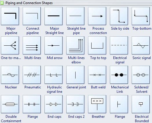
All line types are suitable for representing process piping systems.
Major pipelines connect equipment components across various positions and orientations.
Central straight lines connect equipment positioned on the same horizontal or vertical plane.
Process connections establish flow relationships between equipment. Double-click to edit connection descriptions.
A flange is a projecting rim or collar that strengthens components or maintains positional alignment on rails.
A reducer is a pipeline component that decreases pipe size from larger to smaller bore diameters.
Process Flow Diagram Symbols - Instruments
Process Flow Diagrams utilize standardized symbols and circles to represent instruments and their interconnections within systems.
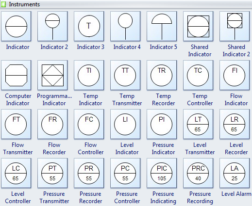
An indicator displays the current state or level of process variables.
A thermometer measures and indicates temperature readings within processes.
A flow transmitter measures substance flow rates through pipelines or tubing systems.
A pressure transmitter typically measures gas or liquid pressure within systems.
A pressure recorder documents and tracks pressure measurements over time.
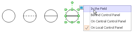
Users can easily modify instrumentation symbols using quick action buttons during diagram design.
Process Flow Diagram Symbols - Centrifuges
A centrifuge separates insoluble particles from solutions through high-speed rotation based on particle size, density, viscosity, medium shape, and rotor speed parameters.
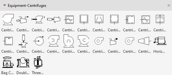
TYPES:
- Benchtop centrifuge
- Continuous flow centrifuge
- Refrigerated centrifuges
- Hematocrit centrifuge
- High-speed centrifuge
- Low-speed centrifuge
- Gas centrifuge
- Microcentrifuge
Process Flow Diagram Symbols - Heat Exchangers
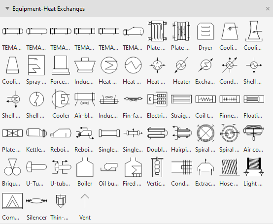
Heat exchangers transfer thermal energy between separated fluids or gases through conductive barriers. These devices serve both heating and cooling applications across various industries. Their primary function involves efficient heat transfer between mediums while maintaining physical separation.
TYPES:
- Shell and tube heat exchangers
- Double pipe heat exchangers
- Condensers, evaporators, and boilers
- Plate heat exchangers
Process Flow Diagram Symbols - Crushers
Crushers are industrial machines that reduce large rocks, stones, and ores into specific sizes and shapes. They are essential in aggregate production, construction materials, recycling operations, and mining industries. Crushers utilize metal surfaces to break, compress, or deform materials into smaller fragments or denser masses.
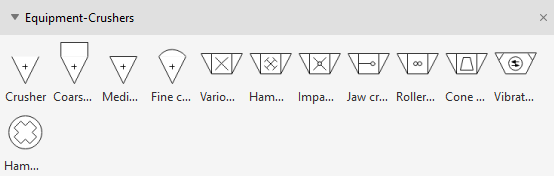
TYPES:
- Jaw crushers
- Gyratory crushers
- Cone crushers
- Compound crusher
- Crusher buckets
- Mineral sizers
- Vertical shaft impactors
Use EdrawMax for Easy Process Flow Diagram Creation
EdrawMax offers extensive symbol libraries compatible with mechanical and industrial requirements for piping, instrumentation, and process documentation.
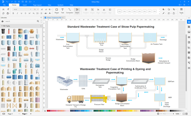
A Process flow diagram utilizes standardized symbols representing various functions, steps, and process phases. It illustrates sequence and interconnection through lines and arrows between process steps. This visual documentation helps project stakeholders identify process stages and understand their relationships.
EdrawMax is professional industrial software for creating process flow diagrams, workflow charts, general flowcharts, and technical diagrams. It provides thousands of industry-standard templates with graphical elements, including symbols, interface points, labels, callouts, and text boxes, to document every process phase comprehensively.
Related Articles


