Guides for Electrical Drawing Reading
Create Professional Electrical Diagrams Effortlessly
EdrawMax Electrical Diagram Software helps you design professional-grade electrical schematics with intuitive templates and a comprehensive symbol library. Start your free trial today!
Part 1: Electrical Diagram Interpretation Guide
1. Master Standard Electrical Symbols
Understanding fundamental electrical symbols is crucial for both interpreting and troubleshooting circuit diagrams efficiently.
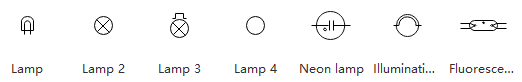
Lamp: Represented by a circle enclosing a cross. This symbol indicates a lighting component that illuminates when current flows through it.
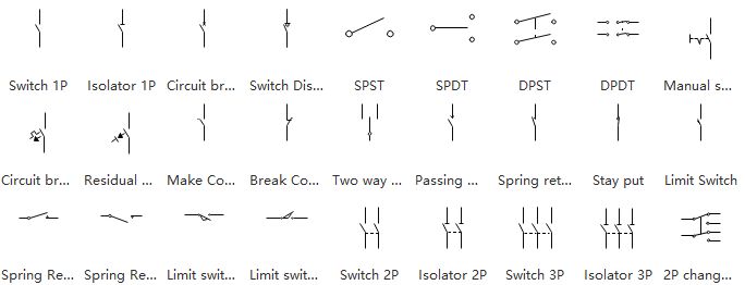
Switches: Depicted as a line break symbol. The design mimics the action of physically flipping a switch to open or close a circuit.
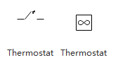
Thermostat: A temperature-sensitive switch symbol that activates based on environmental temperature changes.
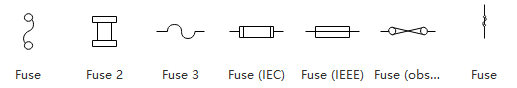
Fuse: Illustrated with a slight zigzag line, representing a protective device that breaks the circuit during excessive current flow.
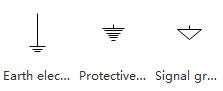
Ground: Shown as either a downward-pointing triangle or descending parallel lines. This symbol represents the circuit's common reference point in schematic diagrams, not necessarily earth ground.
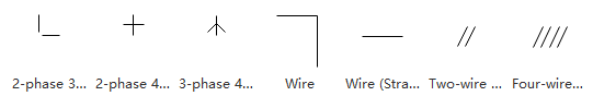
Wires: Straight lines connecting components. While wires may cross in diagrams, connection is only indicated by a dot at the intersection point. Non-connected crossings show one wire arcing over the other.
Design Professional Electrical Diagrams with Ease
EdrawMax Electrical Design Software provides comprehensive tools for creating wiring diagrams, circuit schematics, electrical layouts, and residential wiring plans. Experience professional results with our free trial!
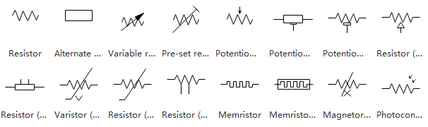
Resistors: Components that limit current flow, represented by zigzag lines. Their resistance value determines how much they impede electrical flow in the circuit.
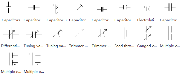
Capacitors: Used for filtering rapid signal changes in modern circuitry. These components typically divert electrical noise to ground while preserving the integrity of the main signal.
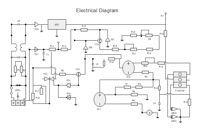
2. Diagram Reading Methodology
Electrical schematics follow a standard reading pattern from left to right and top to bottom, mirroring the signal flow through the circuit. This systematic approach helps technicians understand how components interact within the system.
3. Polarity Identification
Many circuit components have polarity, with distinct positive and negative terminals. The physical component typically indicates polarity through lead length (longer lead = positive) or marked indicators. Symbol representations also often include polarity markings.
4. Component Identification
Component values define their electrical characteristics (ohms, farads, henries) or functional identity (chip names, frequencies). Each component has a unique identifier combining letters (denoting type) and numbers (specific instance), such as R1 for the first resistor.
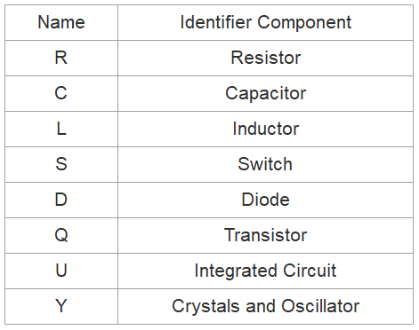
Standard component naming conventions for electrical diagrams
Component naming in electrical schematics follows industry conventions where prefixes indicate component types (R=resistor, C=capacitor, etc.) and numbers distinguish between multiple instances of the same component type.
This standardized naming system creates clear references throughout schematics. While some prefixes are obvious (R for resistor), others are historical (L for inductor since I was already used for current). The reference table above shows common component prefixes used in electrical diagrams.
EdrawMax Electrical
Professional Electrical Design Software >>
- Access an extensive library of standardized electrical symbols and components
- Create dimensionally accurate layouts with professional annotation tools
- Design over 280 diagram types for diverse engineering applications
- Full cross-platform compatibility (Windows, macOS, Linux, Web)
Part 2: Electrical Diagram Creation Tutorial
Apply these electrical symbols to create professional diagrams. Clear component labeling benefits both beginners and experienced engineers in rapid circuit comprehension. Explore more examples in our Engineering Template Gallery.
New to electrical diagrams? Watch our step-by-step video tutorial on creating professional schematics with EdrawMax!
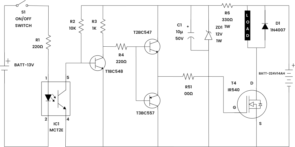
Basic Electrical Schematic
Residential Wiring Diagram
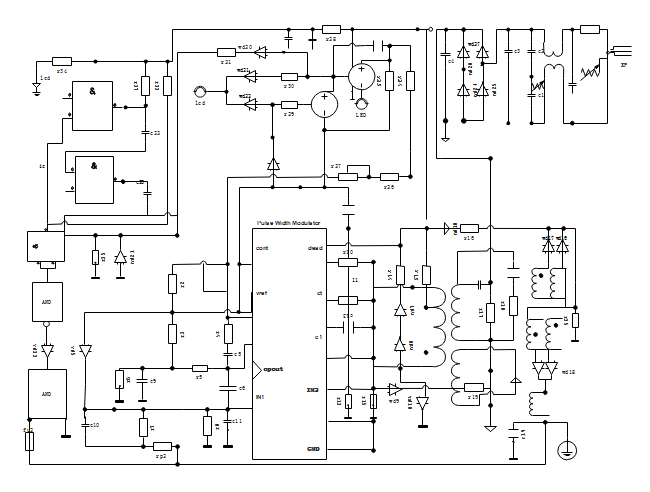
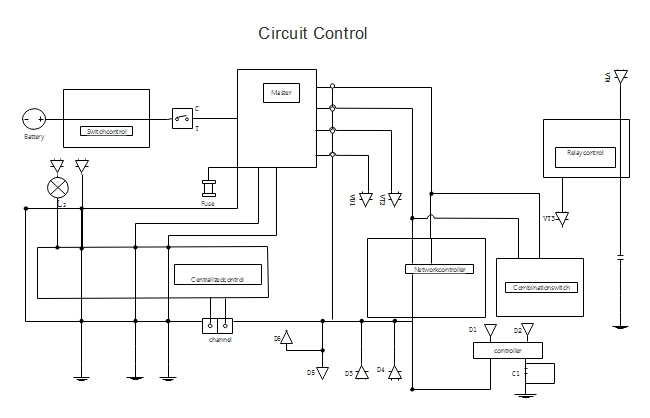
Circuit Control Schematic
Expand Your Electrical Design Knowledge
Electrical Diagram Fundamentals


