Schematic Diagram
Ready to Create Your Schematic Diagram?
EdrawMax is the expert in professional diagramming and visualization. This article provides all the knowledge you need about schematic diagrams. Get started now and try it free!
- What is a Schematic Diagram?
- History of Schematic Diagrams
- Purpose and Benefits
- Use Cases of Schematic Diagrams
- Schematic vs. Circuit Diagram
- Schematic vs. Pictorial Diagram
- Schematic Diagram Symbols
- What to Do Before Creating a Schematic Diagram
- How to Make a Schematic Diagram in EdrawMax
- Schematic Diagram Examples
What is a Schematic Diagram?
A schematic diagram is a simplified, visual representation of a project plan. It uses lines and generic icons to make a drawing extremely simple and easy to understand. While schematic diagrams are most commonly used for electrical and electronic projects, their application is not limited to those domains. They can be created for many other industries such as construction, chemistry, organizational workflow, and personnel flow.
A graphical illustration that helps viewers understand a concept, plan, or any engineering or business diagram with fewer words and more visuals is a **schematic diagram**. Typically, such a drawing consists of symbols and lines that represent key elements and their connections. In some cases, realistic components are added to make the portrayal more detailed and easier to understand. These types of charts are called semi-schematics.
A **pictorial chart** that reflects the rough idea or skeleton of a plan for a fully functional entity, such as an electronic device, is also called a **Schematic Diagram**. The term 'Schematic' means a model or outline, so any illustration that doesn't include the minute details of a project's blueprint can be considered its schematic diagram.
History of Schematic Diagrams
The concept of **schematic diagrams** originated around 1300 A.D. with the creation of the first geographical map, now known as the Atlas. This same concept was later adapted to draw maps of stars and constellations.
Over time, the structure of schematic diagrams evolved. In the 20th century, a new, modern form of the schematic diagram was born, leaving behind the traditional approach. This new visual chart broke free from restrictions to geological maps or stars, focusing more on engineering illustrations such as circuit diagrams and building constructions.
Purpose and Benefits
The primary purpose of a schematic diagram is to provide a high-level overview of a complete project using simple icons and lines. Because these shapes are generalized, even inexperienced engineers can easily read the chart and move the plan into a practical phase.
In the electrical and electronics fields, the main benefit of a schematic diagram is that it serves as a clear guideline for designers. These designers are responsible for creating the detailed circuit diagrams with all the specific information required to manufacture a fully functional piece of equipment. In short, a schematic diagram simplifies the work for design engineers.
Advantages and Disadvantages of Schematic Diagrams
One of the biggest advantages of a schematic diagram is its ability to convey a clear picture of a concept using basic shapes and lines. When a schematic diagram is shared, viewers can quickly grasp its purpose and understand how to connect the key elements to make the entire system function correctly.
The only demerit of a schematic diagram is that it does not include the intricate details of a circuit or system. For example, a typical schematic diagram of a circuit may not contain every single resistor or capacitor that must be used to manufacture an electronic device.
Use Cases of Schematic Diagrams
Unlike detailed circuit diagrams, a schematic diagram can be applied in various domains. Some of the most common industries that use schematic diagrams for their illustrations include:
- Electrical and Electronics
Schematic diagrams are closely related to the circuit diagrams that electrical engineers draw to represent their designs. Even though a schematic diagram doesn't contain every minute component, the illustration is sufficient to provide a clear picture of the circuit and its functionality.
- Chemistry
Many chemical engineers use schematic diagrams to illustrate how a chemical product can be formed from the reaction of two or more compounds. This helps in assessing the outcome without wasting any physical material or putting human lives at risk.
- Building and Construction Industry
With the help of lines and symbols, civil engineers can draw an elaborate schematic diagram to showcase the idea for a building they are about to construct. It's important to note that a schematic diagram for a building is different from a blueprint. While a schematic diagram includes all the major entities a construction may have, a blueprint shows every single element that needs to be installed to complete a ready-to-move-in premise.
- Business and Organization
A well-drawn schematic diagram is also helpful for illustrating an organizational structure and the workflow of a business. Because each business model functions differently, a schematic diagram shows how all departments of a company are related and work together in conjunction with each other.
Schematic vs. Circuit Diagram
People can often be confused about the differences between a schematic and a circuit diagram. Some of the key distinctions are listed in the following table:
| Schematic Diagram | Circuit Diagram |
|---|---|
| Is used in various industries, including electrical engineering, buildings, constructions, chemistry, and more. | Is used exclusively to illustrate how an electronic or electric circuit must be prepared. |
| Consists of industry-specific lines and symbols to illustrate an idea or concept. | Consists only of the symbols used in the electronics and electrical industry. |
| Does not include icons of the real-world elements. | The use of icons representing realistic components is mandatory to make the diagram understandable. |
| Does not include all details; minor details are left off. | Is detailed in nature and includes symbols for even the most minuscule components. |
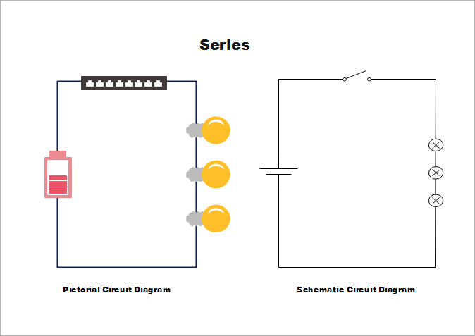
Schematic vs. Pictorial Diagram
Here we will also introduce the differences between schematic and pictorial diagrams, which vary in many details.
| SCHEMATIC DIAGRAM | PICTORIAL DIAGRAM | |
|---|---|---|
| DEFINITION | A Schematic Diagram uses symbolic or abstract symbols instead of pictures to represent a system’s elements. Most irrelevant data is sidelined in a Schematic Diagram. | Among all the diagrams, a Pictorial is the simplest. They use either pictures or sketches to represent components in the diagram. |
| COMPONENTS | The components in the diagram are represented by specific symbols. | To keep things simple, pictures or sketches of the components are used. This gives these diagrams a realistic touch. |
| USAGE | It is used to create an electronic map, which can also be converted into a PCB. They are also used to form a circuit board or to create or modify a system. | It is used to display an already existing system on a 2D level using pictures or sketches. It is used to understand a system in simpler terms and cannot be used to create or modify one. |
| DETAIL INCLUSIVE | The Schematic Diagram avoids irrelevant data and uses symbols, keeping the detail to a minimum. | The use of pictures and sketches ensures the diagram is properly detailed. |
| USERS | These are used by professionals like chemists, electrical engineers, and electronics experts. All fields using these require a proper understanding of the symbols. For example, an electronics expert uses a schematic diagram to make the base of a PCB used for chips and microcontrollers. | Since they are simple and use pictures to depict components, they can be used by handymen and even homeowners to identify components. The pictures and wires in the diagram help them understand the system in simpler terms. |
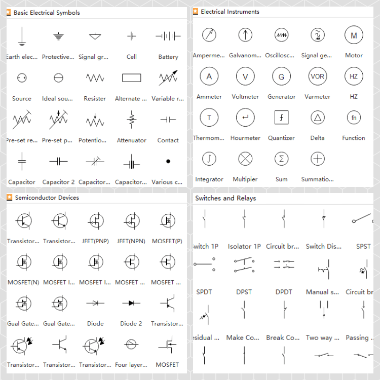
Schematic Diagram Symbols
As mentioned earlier, a schematic diagram is prepared using basic lines and standardized icons that represent the major objects of the equipment to be built. Some of the most common symbols used in a schematic diagram are:
What to Do Before Creating a Schematic Diagram
While creating a schematic diagram is straightforward, there are a few things you should have ready to prepare an effective chart. These include:
- A Rough Idea of the Final Product
Using a circuit diagram as an example, it is essential to have a rough idea—preferably written down—of what you plan to manufacture. This provides a clear direction for your creation process.
- A List of Components
Even though a schematic diagram doesn't include all the minor details, it's important to have a list of all the components required for the device. This gives you a clear idea of which entities to include in the illustration and which ones can be left out for a more detailed version of the drawing.
- A PC Application
While you can draw a schematic diagram manually, it is much more effective to use an efficient computer program like EdrawMax by Wondershare. EdrawMax not only speeds up your chart creation process but also helps you create a professional design using the correct symbols from its built-in libraries.
How to Make a Schematic Diagram in EdrawMax
Wondershare EdrawMax is a powerful tool for diagramming and vector illustrations. The software can be installed on Windows, Linux, Mac, and Chromebook computers and features several categories for different industries, templates for each domain, and multiple built-in libraries containing almost all relevant shapes and icons to produce the best visuals for your projects.
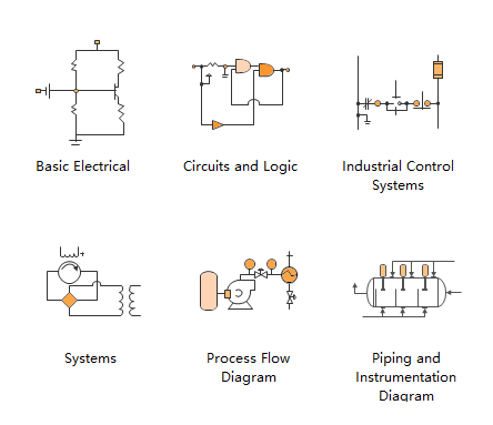
It works at the following electrical drawing types:
EdrawMax makes it easy to design basic electrical diagrams, circuits and logic diagrams, industrial control systems, process flow diagrams, process and instrument diagrams, and system diagrams.
You can learn how to create a schematic diagram in EdrawMax by following the instructions below:
Note: A circuit diagram is used here for demonstration.
Step 1: Pick a Related Template
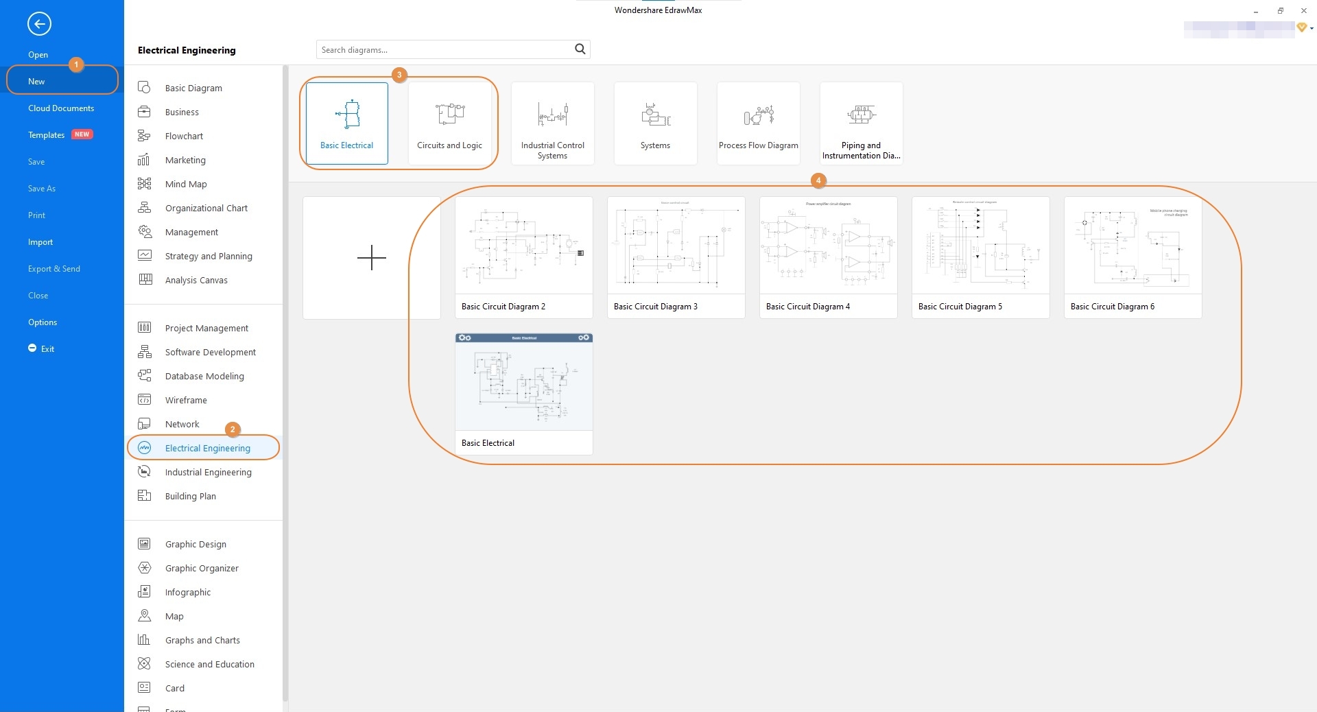
Launch Wondershare EdrawMax on your computer (a Windows 10 computer here). In the left navigation bar, select "New." From the center pane, click on "Electrical Engineering," then choose "Basic Electrical" (used here) or "Circuit and Logic" from the top row of the right window. From the lower section, click to choose a template that is closely related to your project.
Step 2: Customize the Diagram
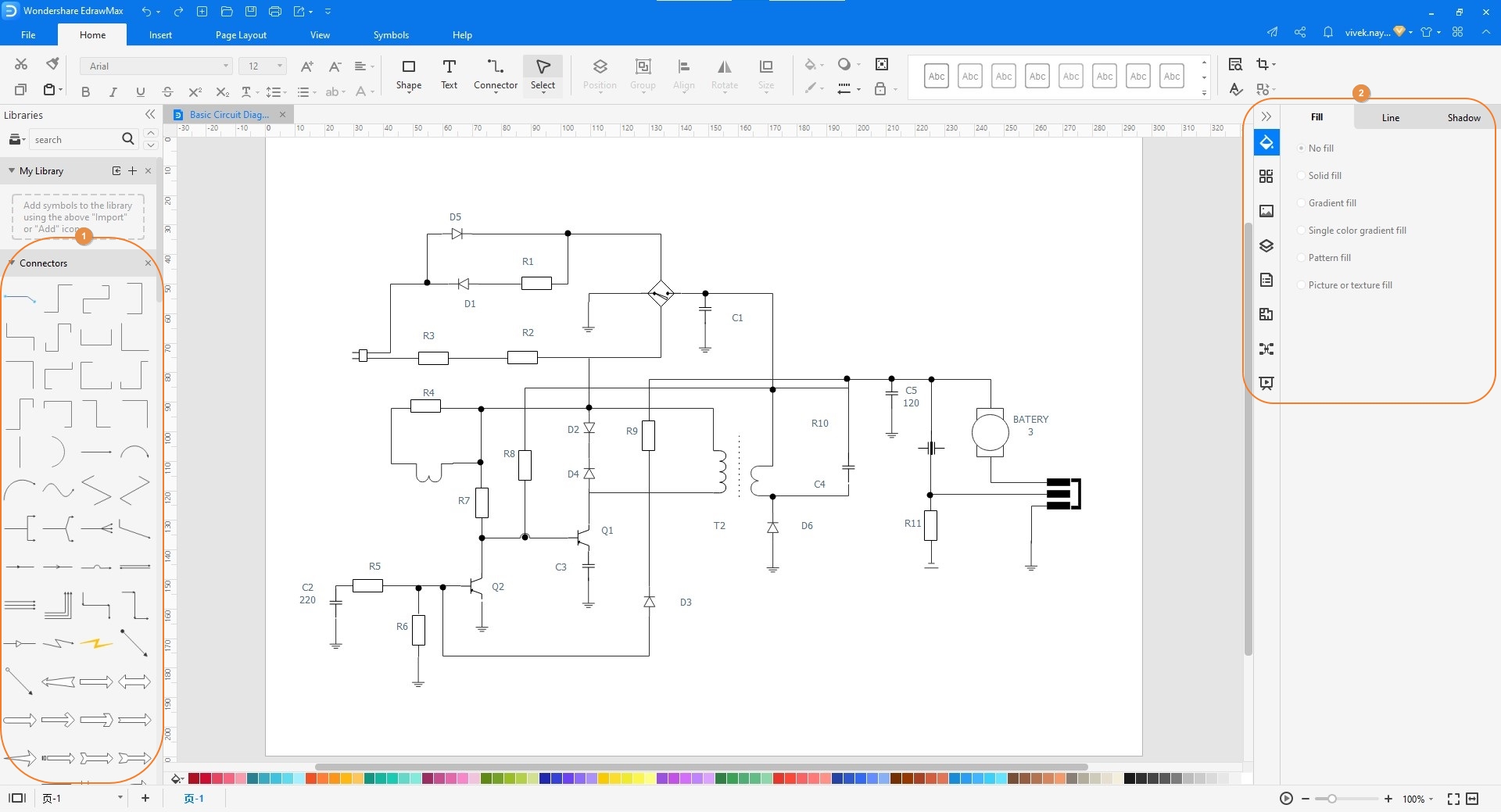
Drag shapes from the libraries on the left to the canvas to customize your illustration as needed. You can double-click any item to add or change its caption. The pane on the right allows you to format shapes, add colors, and make other cosmetic modifications to create a professional and appealing drawing.
Step 3: Save and Export
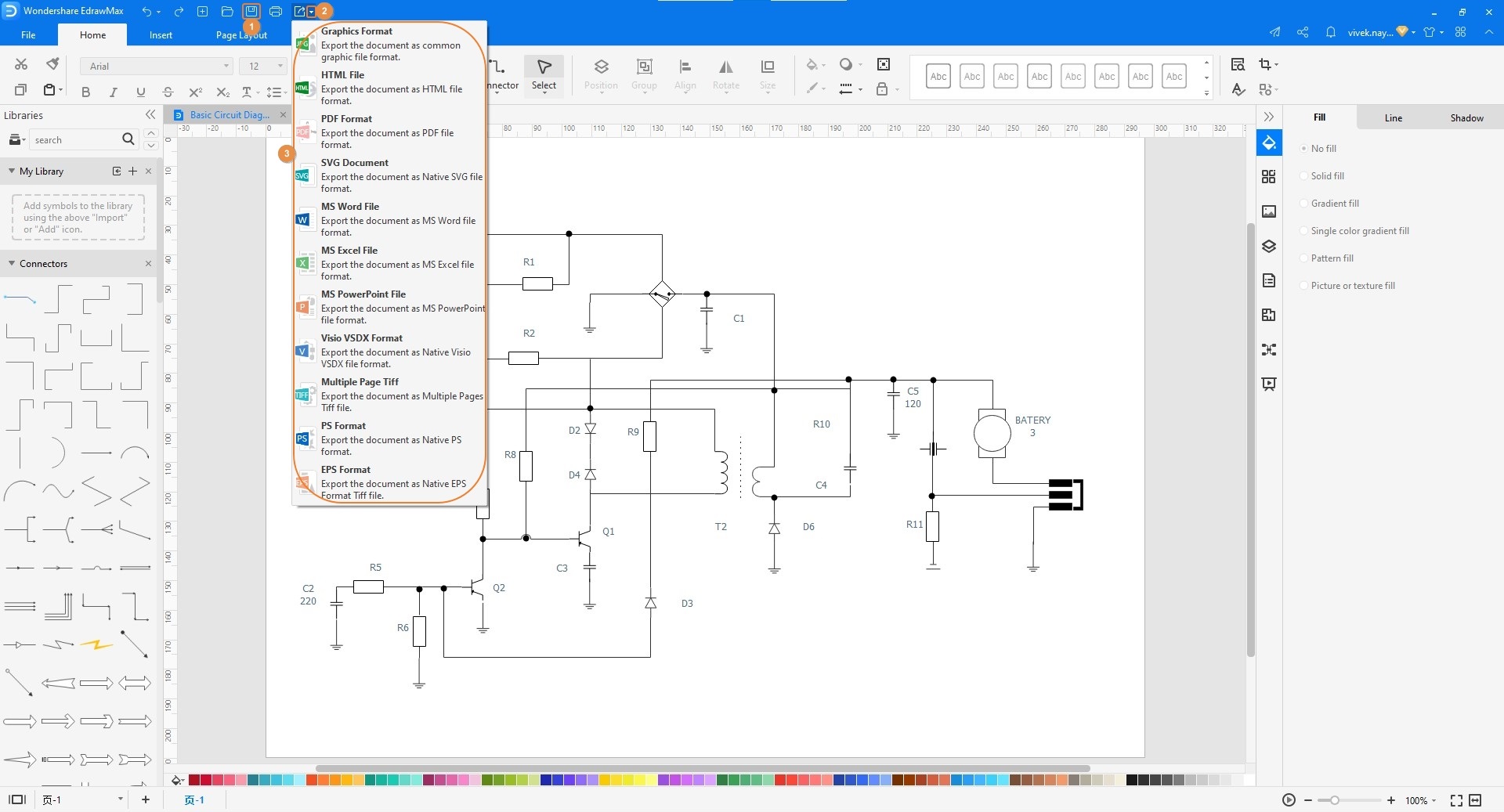
Click the "Save" button from the Quick Access toolbar at the top-left corner of the interface. To export your schematic diagram, click the "More" button on the "Export" icon, choose your preferred format from the list, and follow the on-screen instructions.
Tips for Creating an Effective Schematic Diagram
Here are a few important tips from experienced professionals for creating effective and appealing schematic diagrams:
- Avoid using overly complex shapes and icons. Remember that a schematic diagram is meant to be simple, using generic symbols and lines.
- Do not add minor components. A schematic diagram is an overview of a plan, which differs from a detailed circuit diagram.
- Consider using arrows to show the flow of data or current within the project.
- Add brief descriptions wherever required to provide clarity.
- Use an efficient computer program like EdrawMax to create a professional illustration and avoid human errors.
Schematic Diagram Examples
Example 1:
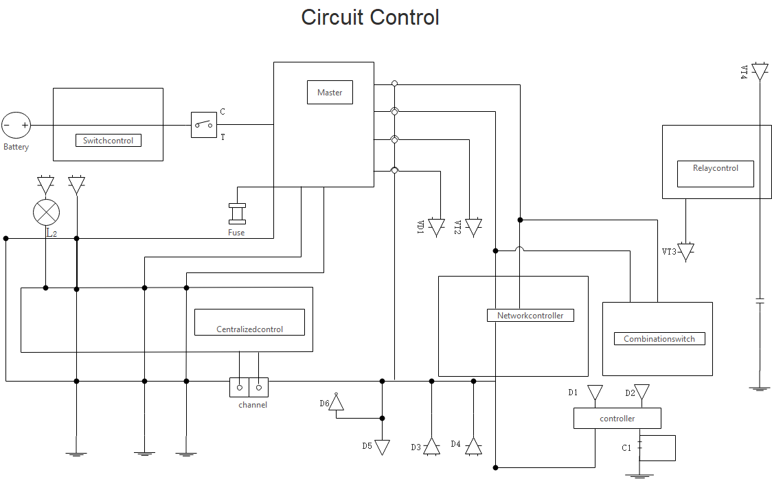
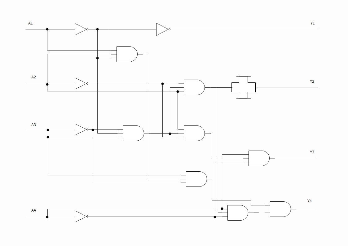
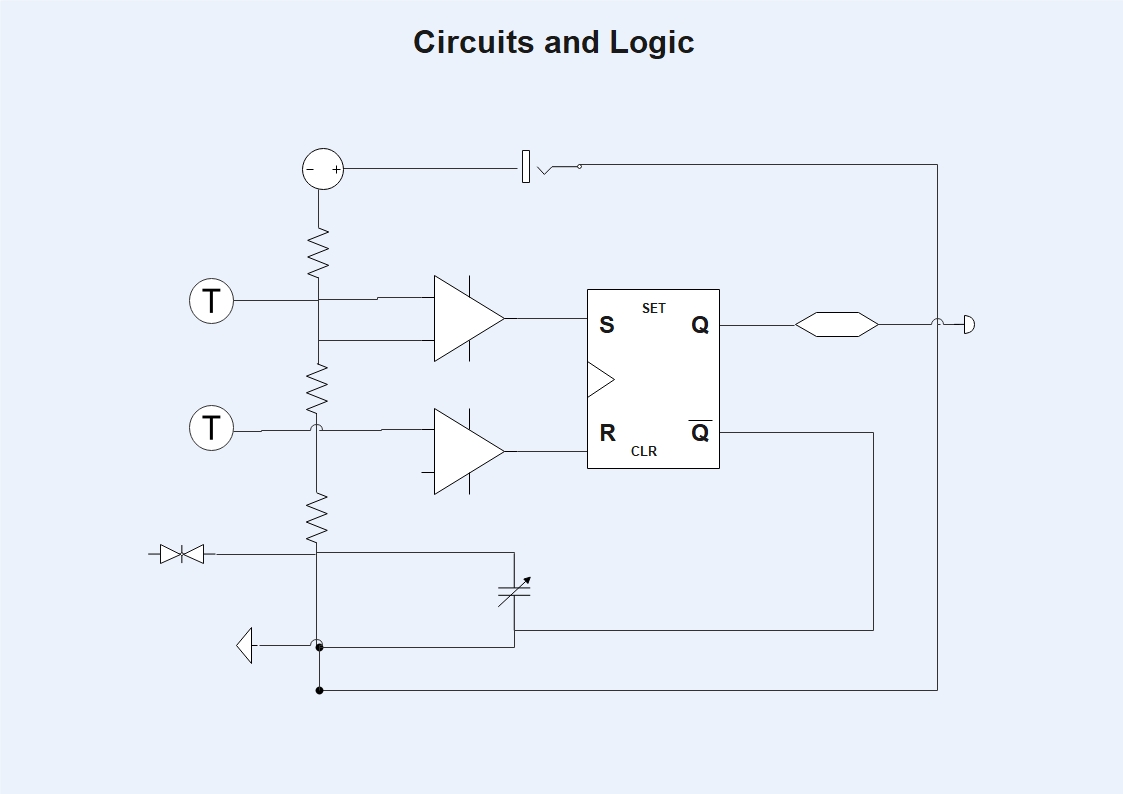
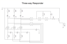
This image is an example of a simple schematic diagram. The lines represent the buses that connect the logic gates, and the symbols of the logic gates are not overly complex. This makes the entire illustration easy to understand, allowing engineers to predict the output more quickly.
Example 2:
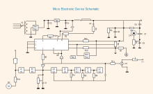
This sample image includes common symbols for resistors, ICs, and logic gates. The connections between elements are shown with lines, which are called buses in circuit diagrams. The switch connected at the top represents the control system used to activate and deactivate the circuit.
More Schematic Diagram Templates
Our schematic diagram software includes several well-formatted templates to help you get started as quickly as possible. Click one of the following templates and customize it to match your needs.
 |
 |
 |
| Basic Electrical Diagram | Circuit Control Diagram | Semiconductor Electron Diagram |
 |
 |
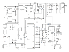 |
| Three-way Responder Diagram | Electronic Device Schematic Diagram | Electrical Wiring Diagram |
The Bottom Line
While **schematic diagrams** are closely related to and are often drawn for circuit illustrations, they are not limited to the electrical and electronic industries. In fact, a schematic diagram can also be drawn for buildings, construction, organizations, and chemistry. While you can create a schematic diagram manually, it is more efficient to use a powerful computer software like EdrawMax. It not only saves you time but also gives you access to a library of globally recognized, correctly drawn symbols.

More Related Articles


