Electrical Symbols
Part 1: What Are Electrical Symbols?
Electrical symbols are the standardized graphical representations of components, devices, and functionalities in an electrical circuit. They are essential for creating circuit diagrams and wiring plans, enabling engineers and designers to accurately visualize and plan a circuit before physically building it. These symbols make the representation of complex circuits clear and easy to understand.
If you're looking to design an electrical diagram but don't know where to start, EdrawMax can provide the help you need.
EdrawMax
Powerful Electrical Diagram Maker >>
- Superior file compatibility: Import and export drawings to various file formats, such as Visio.
- Cross-platform support: Available on Windows, Mac, Linux, and Web.
Part 2: Types of Electrical Symbols
There are a wide variety of electrical symbols, including common and historical electronic symbols. Users can also follow different standards, such as IEEE, IEC (International Electrotechnical Commission), ANSI, JIC, Australian Standard, and more.
Basic Electrical Symbols

A ground symbol or terminal serves as protection against electrical shock. It is a zero-potential reference point from which current is measured.

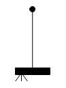
An antenna is a device or rod designed to capture various waves and signals, including electromagnetic waves and electric signals.

A battery symbol has two disjointed and disproportionate parallel lines. The lines signify the series cells within the battery.

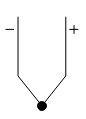
The source is a power supply for an electronic device. Plus and minus signs indicate DC, while a wave signifies AC.
A fuse protects a circuit from burning out by disconnecting it when the current flow exceeds a set limit. The fuse contains a wire that melts to break the connection.

An inductor or reactor is a coil placed in a magnetic field or flux to conserve energy.
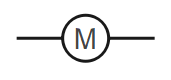
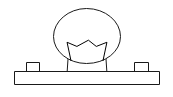
A motor is an electronic device that transforms electrical energy into mechanical energy.
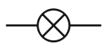
Bulb
A bulb symbol is a circle with a cross in the middle. It signifies a light source that provides an output when current passes through it.

Transformers are used in an AC circuit after being coupled by magnetic flux. They reduce the voltage in a circuit while maintaining the frequency.

A coaxial plug in an electrical circuit acts as a transmission line. It delivers radio frequency and cable television signals. The symbol looks like a circle with an arrow on top and another arrow passing through it.

Switches come in a variety of types, such as single-pole single-throw, pushbutton, dip, and relay. A switch connects a circuit when closed and disconnects it when open.

Resistors in an electrical diagram look like wavy lines with pointed ends. Resistors control the current flow in a circuit by dividing voltage and terminating transmission lines, among other functions.
Capacitor
A capacitor symbol has two terminals with two plates. A curved plate identifies a polarized capacitor, which has a lower voltage.
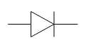
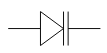
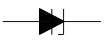
Diode
A diode is a device that allows current to flow in only one direction, as it is polarized with an anode and a cathode side.
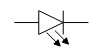
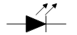
Diode LED
The Diode LED symbol is similar to a standard diode symbol but includes small arrows that indicate the radiation of light.
Draw Schematic Diagrams with a Full Library of Electrical Symbols!
You need the EdrawMax Electrical Diagram Maker to design a circuit. You can get started in minutes with a wide range of electrical symbols and templates! Give it a shot!
Wires
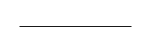
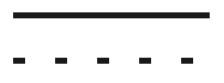
A straight line in an electrical diagram represents an electrical wire or power line, which serves as the conductor of electric current.
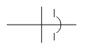
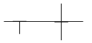
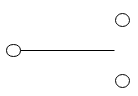
Not Connected Wire
The symbol for a non-connected wire indicates that two wires in a circuit do not intersect electrically. This is represented by two parallel lines, with one line forming a half-circle where it crosses the other.
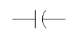
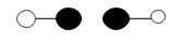
Connected Wire
A connected wire in a circuit allows current to travel from one point to another. The symbol represents a connection between two conductors.
Switches

A Single Pole Single Throw (SPST) switch is a simple ON/OFF switch. The number of poles indicates how many separate circuits it can connect.
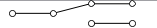
SPDT Toggle Switch
A Single Pole Double Throw (SPDT) switch directs the current flow in a circuit to one of two different directions.

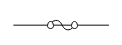
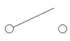
A normally open (N.O.) pushbutton switch requires the button to be pushed to turn it ON. Otherwise, the circuit remains open.

Pushbutton Switch (N.C.)
A normally closed (N.C.) pushbutton switch is typically ON, and the user must press and hold the button to turn it OFF.
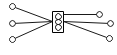
DIP Switch
A DIP (Dual In-line Package) switch allows the user to select one of several voltage options (e.g., from 0 to 5 volts). These switches are not grounded and require external sources.
SPST Relay
An SPST relay has four terminals: two for connecting or disconnecting the circuit and two for the internal coil.

Jumper
A jumper switch is a small metal connector that functions as a simple ON/OFF switch. They are widely used for hardware device configurations.
Solder Bridge
Solder bridges act as permanent switches. When a user solders the two parts of the bridge, the connection is shorted. To disconnect, the user must desolder it.
SPDT Relay
An SPDT relay switches between two circuits and has a coil, a common terminal, a normally closed terminal, and a normally open terminal. If the coil is closed, the common terminal and the normally closed terminal work together.
Download EdrawMax Electrical Diagram Maker
Sources / Power Supply Symbols
This symbol represents an AC (Alternating Current) supply. The current flow continuously changes direction.

A DC (Direct Current) supply provides electric energy in a circuit where the current flows in a single direction.
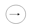
A constant source is an independent current source that provides a consistent current flow.

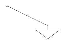
A controlled current source's output depends on the input current. It either delivers or absorbs current within an electrical circuit. The symbol includes a circle with an arrow indicating the direction of current flow.
A controlled voltage source in a circuit is represented by a diamond shape with positive and negative signs. The voltage in the circuit controls these sources.
A single-cell battery is depicted by two unmatched parallel lines, one large and one small, representing a single cell.
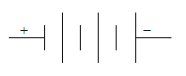
A multi-cell battery has multiple small and large lines, which represent multiple cells acting as cathodes and anodes.

A generator in a circuit can function as either a voltage source or a current source, depending on the circuit design.
Ground
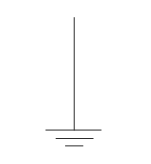
Earth ground is a zero-potential ground that has the potential to conduct to the earth.
A chassis ground protects a user from electric shock by creating a barrier between the user and the circuit.
This is an arbitrary reference point relative to the earth's ground potential.
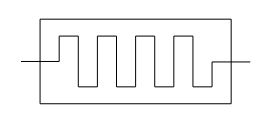
Resistor and Variable Resistor
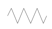
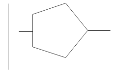
This is the IEEE symbol for a fixed resistor, represented by a wavy line with pointed ends connected to two points.
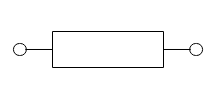
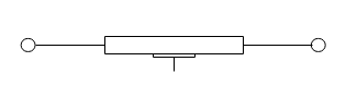
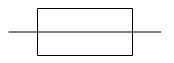
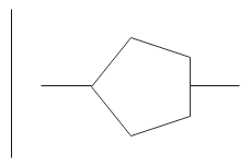
A resistor is a two-terminal device, and the IEC standard symbol looks like a rectangular bar connected to two points.
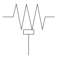
This is a three-terminal resistor that creates an adjustable voltage in an electrical circuit.
This is a three-terminal resistor that creates an adjustable voltage in an electrical circuit.
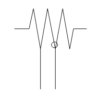
A tapped resistor uses one or more terminals to function as a voltage divider in devices.
An attenuator is a circuit component that dissipates current flow to step down the voltage.
A memristor is a semiconductor that functions as a connection point for capacitors, inductors, and resistors.
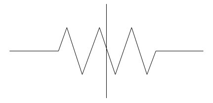
This device creates a variable current by adjusting resistance.
A preset is a component that provides variable resistance to an electrical circuit.
A magneto resistor's resistance changes in response to an external magnetic field.
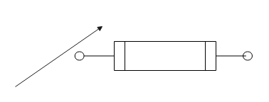
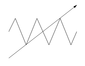
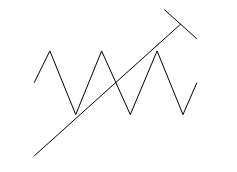
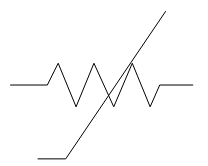
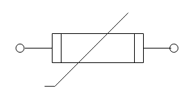
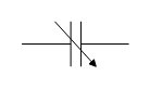
The IEC symbol for a variable resistor features a bar, similar to a standard resistor symbol, with an added arrow to denote its variable nature.
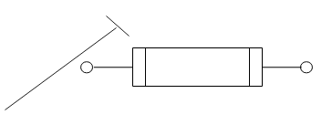
A trimmer resistor, also known as a trim pot, is used to fine-tune a circuit and calibrate new devices.
A thermistor is a type of resistor whose resistance is highly dependent on temperature.
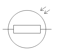
A photoresistor or LDR is a device whose resistance varies with the intensity of light.
Create Circuit Diagrams with a Full Library of Electrical Symbols!
Design professional circuit diagrams in minutes using EdrawMax's powerful Electrical Diagram Maker. Get started now with a wide variety of electrical symbols and templates!
Capacitors
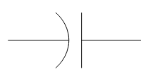
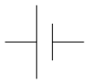
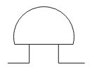
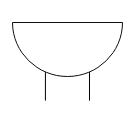
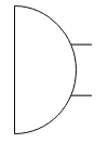
A capacitor is an electrical component that stores energy in an electric field. This symbol shows a straight line and a half-circle side-by-side.
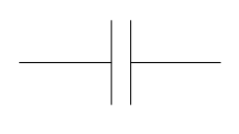
An unpolarized capacitor is represented in a circuit by two parallel lines with connecting lines on either side.
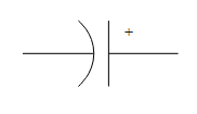
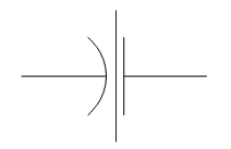
This symbol for a polarized capacitor shows a straight plate and a curved one, representing the anode and cathode, respectively.
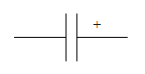
This alternative symbol for a polarized capacitor uses two separate straight lines, one for the cathode and the other for the anode.
A variable capacitor is a component whose capacitance can be changed, either mechanically or electronically.
A feed-through capacitor, containing a dielectric layer, is designed to carry signals through an enclosed path while filtering out unwanted noise.
Inductors
An inductor is an electronic component that stores energy in a magnetic field when electric current flows through it.
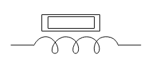
Iron-core inductors have high inductance and are represented by a coil symbol with a rod.
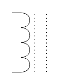
A ferrite-core inductor is symbolized by a coil with two dotted lines, indicating the ferrite core.
A center-tapped inductor is a component with an electrical connection at the center of the coil, often used for signal coupling.
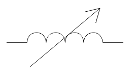
A variable inductor, which has adjustable inductance, is represented by an inductor symbol with an arrow to indicate its variable nature.
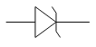
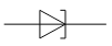
Diodes
A diode is an electronic device that allows electric current to flow in only one direction.
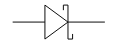
A Zener diode is a specialized diode designed to maintain a stable voltage across its terminals.
A Schottky diode is a semiconductor diode with a very low forward voltage drop and fast switching speed.
A varicap diode is a type of diode whose capacitance changes significantly with applied voltage.
A tunnel diode is a semiconductor that exhibits negative resistance due to the quantum mechanical effect of tunneling.
An LED is a semiconductor device that produces light when an electric current passes through it.
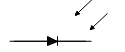
A photodiode is a light-sensitive diode that converts light into electrical current.

This is a four-layer semiconductor device with a PNPN structure, used as a switch.

A thyristor is a solid-state semiconductor device that functions as a bistable switch.
A constant-current diode is a type of diode that limits or regulates the current flowing through a circuit.

A laser diode is a semiconductor device that converts electrical energy into coherent light through stimulated emission.
Download EdrawMax Electrical Diagram Maker
Transistor
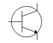
An NPN bipolar transistor allows current to flow from the collector to the emitter when a small current is applied to the base.

This transistor controls the flow of current from the emitter to the collector. It is the opposite of an NPN transistor.

This is a compound structure containing two bipolar transistors connected to provide a very high current gain.
JFET-N transistors use electrons as the primary charge carriers within a circuit.
This transistor is primarily made of P-type material with two smaller N-type regions, using holes as charge carriers.
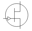
NMOS transistors operate by creating an inversion layer of n-type material in the p-type body of the transistor to allow current flow.
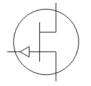
PMOS transistors operate by creating an inversion layer of p-type material in the n-type body of the transistor to allow current flow.
Logic Gates
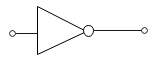
A Not Gate, or inverter, has a single input and produces an output that is the inverse of the input. A "high" input yields a "low" output, and vice versa.
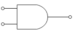
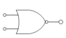
An AND Gate can have two or more inputs. The output is true (high) only if all inputs are true (high).
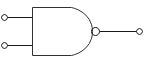
A NAND Gate can have two or more inputs. The output is false (low) only if all inputs are true (high).
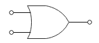
An OR Gate can have two or more inputs. The output is true (high) if at least one of the inputs is true (high).
A NOR Gate can have two or more inputs. The output is true (high) only if all inputs are false (low).
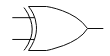
An XOR (Exclusive OR) Gate has two or more inputs. The output is true (high) if an odd number of inputs are true (high).
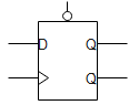
A D-Flip-Flop is a logic gate that stores one bit of data. It has a data input and a clock input, with two outputs (Q and its inverse, Q').
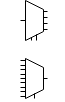
A multiplexer (MUX) is a logic gate that selects one of several input signals and forwards it into a single output line.

A demultiplexer (DEMUX) takes a single input signal and distributes it to one of several output lines.

A tri-state buffer is a logic gate that allows for a high, low, or high-impedance (disconnected) output state.
Amplifier

The symbol for a basic amplifier is a triangle with one input and one output, signifying a component that increases the strength of a signal.
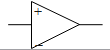
An operational amplifier (Op-Amp) is a voltage-amplifying device with two input pins and a single output pin, used to amplify weak electrical signals.
Create Professional Circuit Diagrams with a Wide Range of Electrical Symbols!
Design and build circuit diagrams effortlessly with EdrawMax, a powerful electrical diagram maker. Access thousands of symbols and templates to get started quickly and accurately.
Antenna
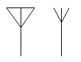
This is a generic symbol for an aerial antenna, typically depicted with three open lines at the top.

This antenna symbol uses two conductors of equal length, resembling two parallel lines.

This antenna symbol is shown as a loop and is used to represent a loop antenna in a circuit.
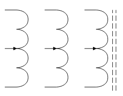
Transformers
Transformers are used to increase or decrease AC voltage. This symbol consists of two coils with wire linked to them.

This symbol represents a transformer with an iron core, shown as two parallel lines between the coils.

These transformers have an additional connection point, or "tap," at the center of the secondary winding, often used for signal coupling on inductors.
Miscellaneous
This device converts electrical energy into kinetic (mechanical) energy.

Transformers are represented by coils wound around a core material.
An electric bell is a device that converts electrical energy into sound energy.
A buzzer is an electronic component that produces sound when an electrical current is applied.
A fuse is a safety device with a wire that melts to break a circuit when current exceeds a safe level.
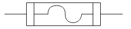
This symbol represents a fuse that disrupts current flow to prevent short circuits and protect components.

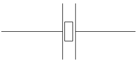
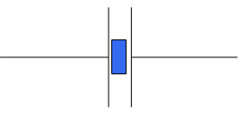
A bus symbol in a circuit diagram denotes the path for power flow.
This bus symbol is used to represent a data or signal pathway within a circuit.
This symbol for a bus looks like a line with a hollow space inside, signifying a connection point in a circuit.
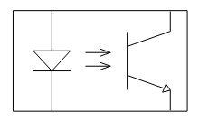
An optocoupler (or opto-isolator) uses light to transfer electrical signals between two separate circuits while keeping them electrically isolated.
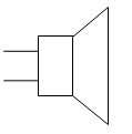
A loudspeaker is a device that converts electrical energy into sound waves.
A microphone is a device that converts sound energy into electrical energy.
This is a simplified symbol for an operational amplifier, which is used to amplify weak signals.
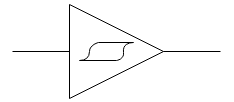
A Schmitt trigger is a comparator circuit that converts an analog input signal into a digital output signal.
This device changes an analog signal into a digital signal.
This device works to convert a digital signal into an analog one.
A crystal oscillator is an electronic circuit that uses the mechanical resonance of a vibrating crystal to create a stable electrical signal with a precise frequency.
This symbol represents a crystal oscillator, which generates a specific frequency for timing circuits.
This symbol signifies a single, unidirectional flow of electrical current in a circuit.
A light bulb is a component that produces light when an electrical current passes through it.
A thermocouple is a temperature sensor that generates a voltage proportional to the temperature change.
Download EdrawMax Electrical Diagram Maker
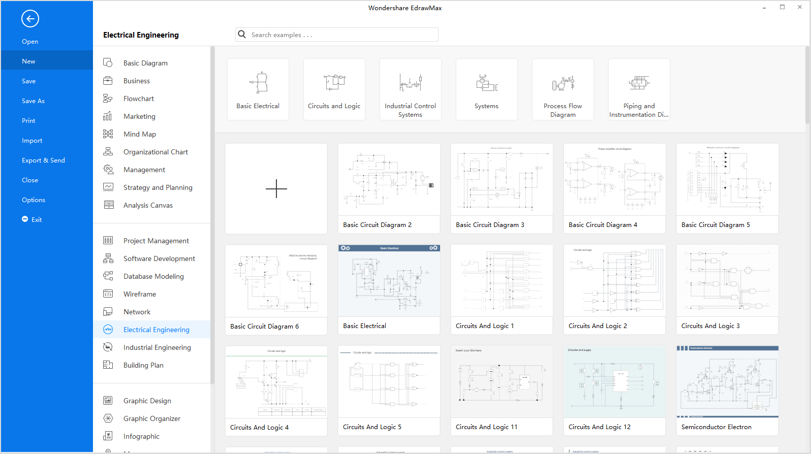
Part 3: How to Use Electrical Symbols
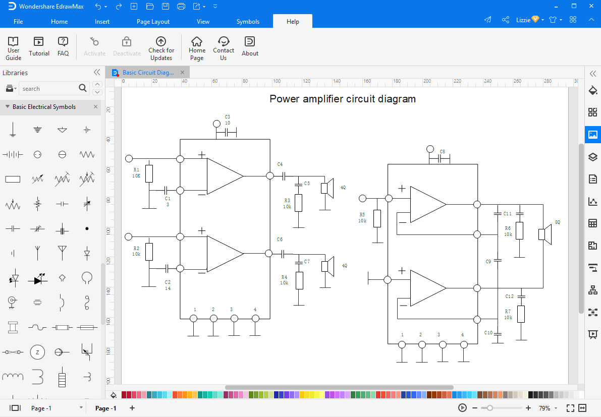
Creating an electrical diagram is straightforward once you know where to find the right symbols. The video below shows you how to create an electrical circuit diagram. You can also follow the step-by-step text and picture instructions.
Wiring and Circuit Diagram Maker: EdrawMax
Electrical symbols make it simple for engineers to create complex circuit diagrams. While there are many tools available, EdrawMax Electrical Diagram Maker offers a user-friendly experience with an extensive library of electrical symbols. Ready-made templates are available to help new users get started easily. Once your project is complete, you can effortlessly export the file in various formats and share it with others.
Step 1: Launch EdrawMax on your computer. An extensive collection of electrical diagram templates can be found in the Electrical Engineering category. Click the Basic Electrical icon to open the symbol library, which contains all the symbols needed to create electrical diagrams.
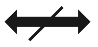
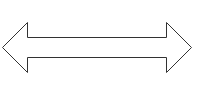
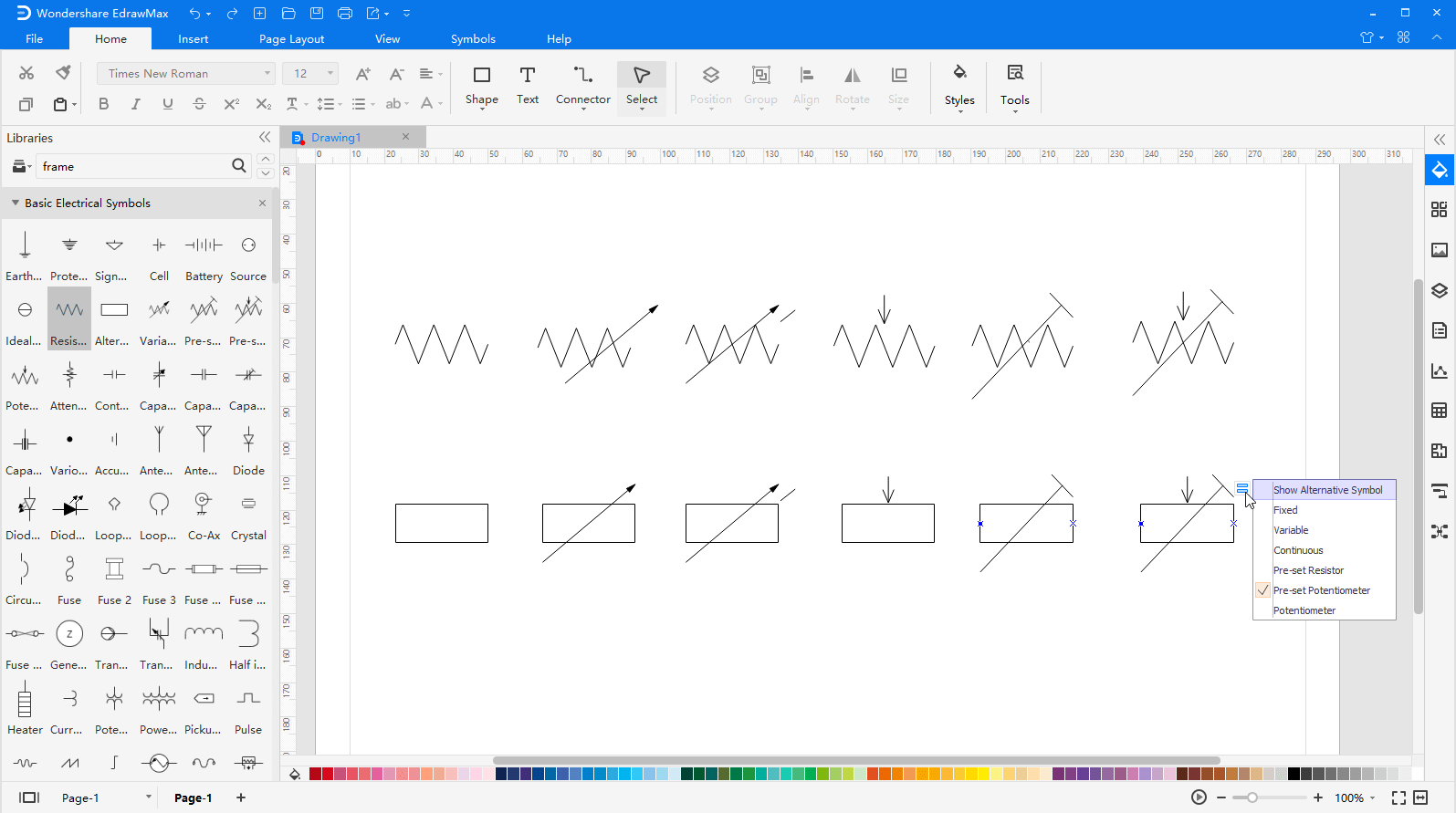
Step 2.1: In the EdrawMax workspace, simply drag the symbol you need directly onto the canvas. You can resize the selected symbol by dragging its handles. A double-sided arrow indicates the direction for resizing, while a four-direction arrow allows you to move the symbol on the canvas.
Step 2.2: You can also change the shape of a symbol using the floating menu or action button that appears when the symbol is selected. For example, a resistor symbol can have up to 12 variations.
Step 3: When your electrical diagram is complete, you can export it to various popular formats such as **JPG, PNG, SVG, PDF, Microsoft Word, Excel, PowerPoint, Visio, or HTML** with a single click. This makes it easy to share your drawings with others, even if they don't use EdrawMax.

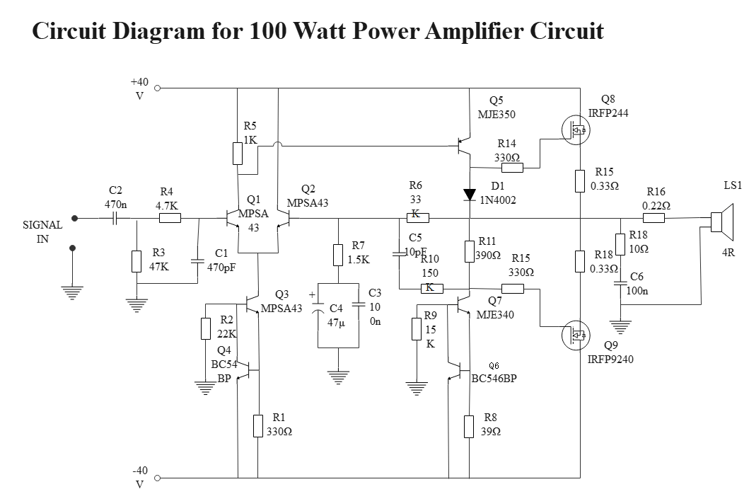
Wiring and Circuit Diagram Example
Here is an example of a circuit diagram for a 100-watt power amplifier. A signal passes through several capacitors and amplifiers, where its strength is increased. The final output is delivered through a loudspeaker.
Part 4: More Electrical Symbols


