Wiring Diagram
What is a Wiring Diagram?
A wiring diagram is a visual representation of all electrical connections within a specific circuit. It uses standardized shapes and symbols to depict different components, providing an effective method for illustrating how wires interconnect with various elements in a system.
How to Use a Wiring Diagram
Wiring diagrams are essential for illustrating connection systems within circuits. They are primarily used by building planners, architects, and electricians to present wiring connections in buildings, rooms, or devices. These diagrams are invaluable for troubleshooting connection faults, installing new wires and devices, locating electrical outlets, and ensuring proper system implementation.
Wiring Diagram vs. Schematic Diagram
Schematic diagrams focus on illustrating the basic plan and function of electrical systems rather than physical location. In contrast, wiring diagrams show how wires connect to devices and their exact physical placement within a circuit. The table below highlights key differences between these diagram types.
| Features | Wiring Diagram | Schematic Diagram |
|---|---|---|
| Electrical Connections | Focuses on physical connections between devices and circuit elements | Focuses on the logical operation of a circuit |
| Symbols | Uses simplified shapes to represent electrical components | Uses abstract, graphic symbols to identify components |
| Lines | Represent physical wiring between components | Represent system flow and power output relationships |
| Purpose | To show physical connection relationships between components | To illustrate electrical functionality and circuit operation |

4 Bit Counter Schematic (wikimedia)
Wiring Diagram vs. Pictorial Diagram
Among electrical wiring layouts, pictorial diagrams are the least practical option. These diagrams combine photographs with highly detailed component drawings to explain wiring, making them understandable only to those with extensive electrical knowledge. In comparison, wiring diagrams are simpler and more accessible for general understanding.
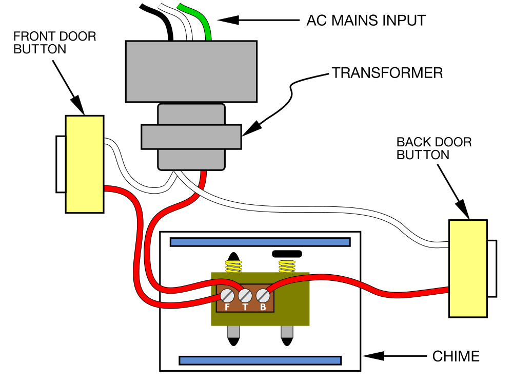
Doorbell Wiring Pictorial Diagram (wikimedia)
Standard Wiring Diagram Symbols
Reading wiring diagrams requires understanding basic symbols, lines, and connections. Fundamental components include wires, bulbs, switches, cells/batteries, resistors, capacitors, logic gates, and more. These symbols are standardized abstract representations of original components for universal comprehension.
Here are the top ten essential circuit symbols everyone should know:
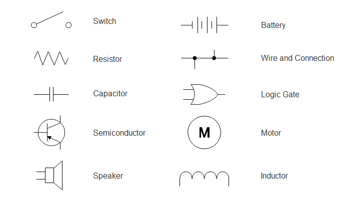
1. Switch: Controls power flow between different components and areas. Symbol variations represent switch types including Push button, Limit switch, 2-way switch, DPST switch, DPDT switch, and SPDT switch.
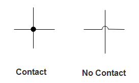
2. Wires: Represent connections between circuit components. Symbols differentiate between joined wires (forming T junctions) and non-joined wires (crossing without connection).
3. Battery: Represents one or more cells joined together to provide power input to a circuit. Batteries are critical components in electrical systems.
4. Resistor: Indicates current flow restriction within a circuit, primarily used for voltage division. Main categories include Variable Resistor and Non-Variable Resistor.
5. Capacitor: Represents a charge-storage device. Symbols differentiate between polarized and non-polarized capacitors. Often paired with resistors to create filters that pass AC signals while blocking DC.
6. Motor: Represents a device that converts electrical energy into kinetic energy.
7. Speaker: Represents a device that converts digital input into analog sound waves, commonly used in televisions, mobile phones, and computers.
8. Inductor: Two-terminal electrical coils that store energy in magnetic fields. Variations include half inductor, position transmitter inductor, and mutual inductor symbols.
9. Logic Gate: Essential components for data storage and output processing. Logic gates process binary inputs (1s and 0s) to produce specific outputs based on their configuration.
10. Semiconductor: Symbols represent diodes, rectifiers, controlled switches, Diac, Triac, and other semiconductor devices.
EdrawMax
All-in-One Diagram Software
- Superior file compatibility: Import and export drawings to various file formats, such as Visio
- Cross-platform supported (Windows, Mac, Linux, Web, Android, iOS)
How to Read a Wiring Diagram
Reading wiring diagrams requires understanding various symbols, lines, and connection types used in electrical schematics.
Step 1: Recognize Wiring Diagram Symbols
Begin by familiarizing yourself with fundamental elements represented in wiring diagrams, including ground, power supply, wires, connections, output devices, switches, resistors, logic gates, and lights. Each component has a specific pictorial symbol for universal recognition.
Step 2: Understand Line Junctions
Lines represent wires connecting components. All points along a wire are connected and identical. Wire crossings don't necessarily indicate connections—black dots signify junction points. Main lines are typically labeled L1, L2, etc., with different colors distinguishing functions. Always consult the diagram legend for color coding explanations.
Step 3: Identify Connection Types
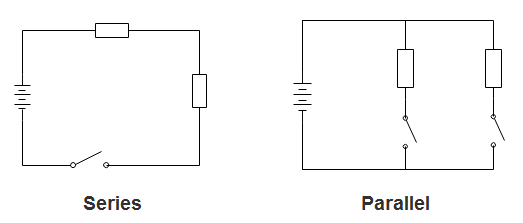
Circuits with multiple components typically use two connection types: series and parallel. In series circuits, components connect along a single path where current flows through each component sequentially. Voltages add up across components while current remains constant. In parallel circuits, each device connects directly to the power source, receiving equal voltage while current divides among parallel branches.
How to Draw a Wiring Diagram
Create professional wiring diagrams easily using EdrawMax.
Step 1: Launch EdrawMax desktop software or access the EdrawMax web-based application.


Step 2: Navigate to [New] > [Electrical Engineering] > [Basic Electrical]
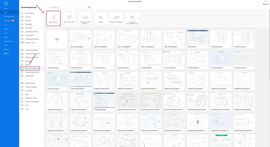
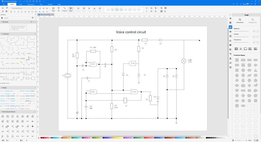
Step 3: Select a wiring diagram template to customize or click [+] to start from scratch. Utilize extensive wiring symbol libraries from the left menu to create your diagram.
Step 4: After completing your design, export in multiple formats including Graphics, PDF, editable MS Office files, SVG, and Visio VSDX.

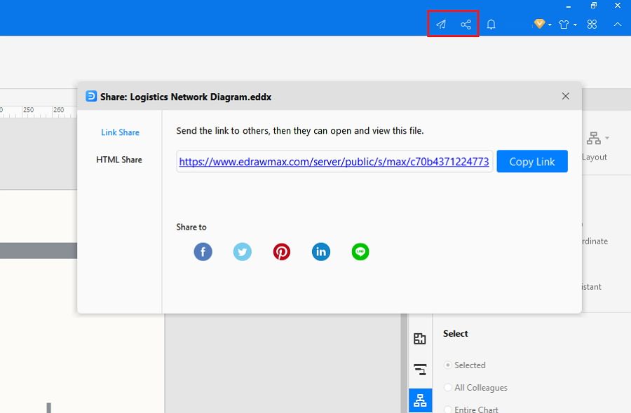
Step 5: Share your diagram via social media or web pages. Publish to EdrawMax's template gallery to showcase your work.
For visual guidance, watch our tutorial video demonstrating how to create professional wiring diagrams with EdrawMax.
Wiring Diagram Examples
Skip the manual drafting process and utilize EdrawMax's free templates to create professional diagrams quickly. With diverse templates and comprehensive tools, you can design wiring diagrams for any application. Explore these top examples:
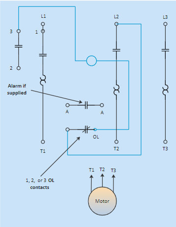
Example 1: Motor Starter Wiring Diagram
This straightforward motor starter wiring diagram shows component positions and connections. Easy to read and understand, it provides clear guidance for controller wiring. Arrows and open terminals indicate user connections.
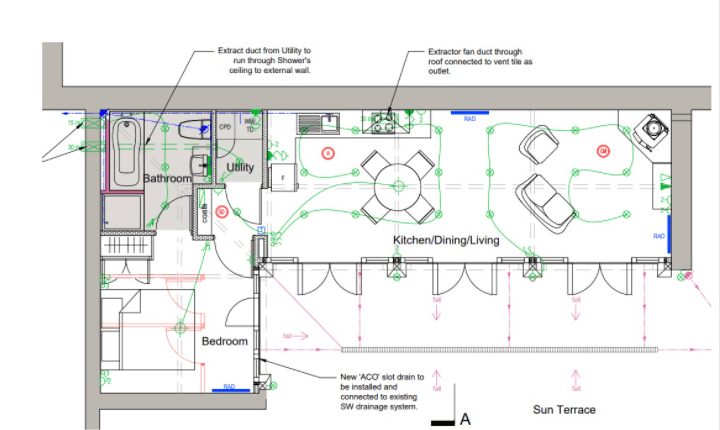
Example 2: Home Electrical Wiring Plan
This detailed residential electrical wiring plan shows internal and external connections through walls and ceilings, addressing major and minor wiring requirements. It comprehensively details power outlets and wire routing throughout the structure, providing invaluable guidance during construction.
Example 3: 3-way Switch Wiring Diagram
This diagram illustrates controlling a device (like a bulb) from two locations using a 3-way switch. It shows three-wire cable between switches and two-wire cable connecting to the bulb.
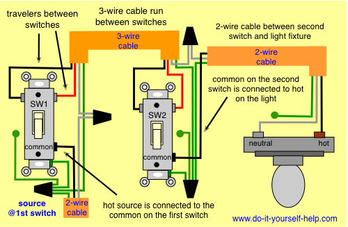
Source: do-it-yourself-help.com
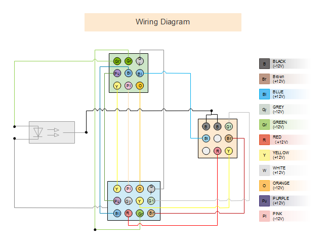
Example 4: Harness Wiring Diagram
This harness wiring diagram demonstrates proper wire matching for each connection within wiring harness assemblies.
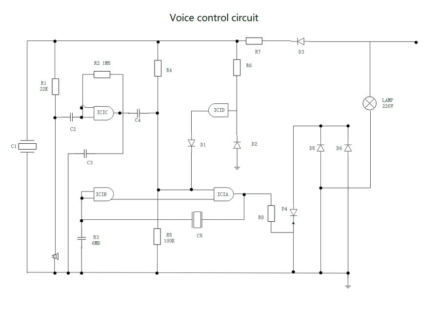
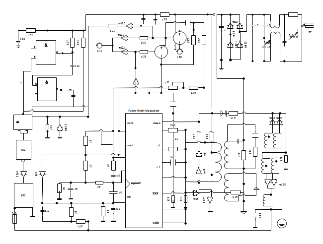
Example 5: Electrical Wiring Diagram
This electrical wiring diagram displays wire connections and the physical layout of an complete electrical system or circuit.
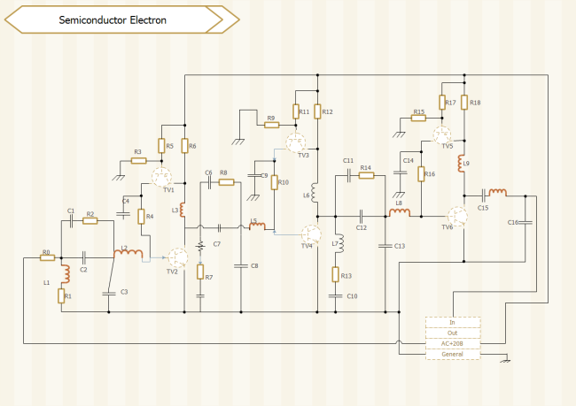
Example 6: Semiconductor Electron Diagram
This diagram illustrates semiconductor components, primarily silicon-based crystals extensively used in electrical circuits.
Design Professional Wiring Diagrams with EdrawMax
EdrawMax is a powerful yet intuitive wiring diagram software that creates professional diagrams using pre-formatted templates and examples—no drawing skills required. Smart wiring symbols feature auto-generation arrows for easy shape addition and connection.
Available for Windows, macOS, and Linux, EdrawMax offers categories for virtually all industries with numerous templates that save time compared to creating diagrams from scratch.
This article has covered wiring diagram fundamentals, symbols, and the efficiency of EdrawMax software, along with practical templates and examples. Creating perfect wiring diagrams with EdrawMax delivers professional results effectively.
As a comprehensive diagramming tool, EdrawMax enables easy creation of wiring diagrams and other diagram types. With extensive symbol libraries and clipart, diagram creation becomes straightforward. Export your work in multiple formats and share with collaborators. Start creating your wiring diagrams today!
Expert Tips:
- Ensure technical accuracy and readability by carefully verifying details like component polarity direction;
- Use correct standardized symbols, paying attention to subtle differences between similar symbols;
- Draw connecting wires as straight lines, using dots for junctions and line jumps for non-connected crossings;
- Label components like resistors and capacitors with their values, maintaining clean text placement;
- Follow conventional layout: positive (+) supply at top, negative (-) supply at bottom, with logical left-to-right flow;
- Optimize component placement to minimize wire crossings for cleaner diagrams.
Related Articles


