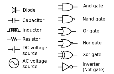
Circuit Diagram Symbols
Ready to Create Your Circuit Diagram?
EdrawMax specializes in professional diagramming. Learn how to create circuit diagrams with ease using our comprehensive guide. Try it free today!
Whether you're a student or a professional in electronics or physics, dealing with circuit diagrams is a daily necessity. Students use them to learn and practice for the job market, while engineers rely on them to create high-quality products for their clients.
Circuit diagrams are incomplete without circuit diagram symbols. These symbols are fundamental components, and a circuit diagram can never be completed without them. In this article, we'll introduce you to the essential circuit symbols you need to know and recommend a powerful software, EdrawMax, for creating your own circuit diagrams with ease.
What Are Circuit Symbols?
So, what are circuit symbols? In the world of electronics, circuit symbols are used to represent various electrical and electronic components in a diagram, such as transistors, grounds, wires, bulbs, batteries, and resistors. Without these symbols, it's impossible to understand or analyze what a circuit diagram is trying to convey. Using these symbols correctly is crucial, and this is only possible when you understand each symbol's function and proper usage.
How Circuit Symbols Form a Circuit Diagram
There are two primary ways to represent a circuit diagram:
- Representing the circuit with symbols.
- Representing the circuit with words.
Representing a circuit with words is straightforward, for example: "The battery is connected to the resistor." However, as diagrams become larger and more complex, using circuit diagrams and symbols is essential for quick and accurate analysis. This is why connecting each symbol forms a complete circuit diagram, simplifying our understanding and saving time.
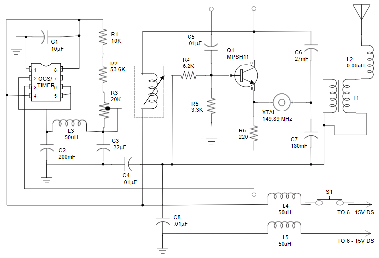
This image shows a circuit diagram for a mobile phone charger. As you can see, using symbols makes it much faster and easier to analyze the basic structure compared to a word-based description.
EdrawMax
All-in-One Diagram Software
- Superior file compatibility: Import and export drawings to various file formats, such as Visio
- Cross-platform supported (Windows, Mac, Linux, Web)


Complete List of Circuit Diagram Symbols
There are countless circuit symbols for the many electronic components available. Each component has a specific symbol, but we will focus on the most frequently used symbols, their functions, and their types.
List of Circuit Diagram Symbols:
Wires
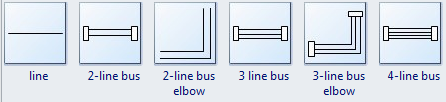
A straight line represents a wire. The primary function of a wire is to connect two or more circuit devices and transfer electricity. Wires are designed for various purposes, leading to different structures. Some common types of wires include:
- Flexible cables
- Direct-buried cables
- Heliax cables
- Metallic sheathed cables
- Non-metallic sheathed cables
Switches
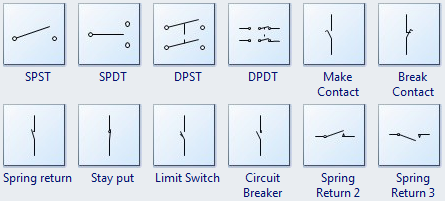
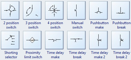
This symbol represents an electrical switch. As the name suggests, switches control the flow of current by interrupting or diverting it from one device to another, turning a device on or off. Common types of switches include:
- Single-pole, single-throw (SPST) switch
- Single-pole, double-throw (SPDT) switch
- Double-pole, single-throw (DPST) switch
- Double-pole, double-throw (DPDT) switch
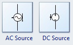
Power Sources
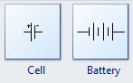
This is the symbol for power sources or batteries. The main function of a power source is to provide electrical current to the connected devices. Without a power source, a circuit cannot function. Types of power sources include:
- AC Power Supply
- DC Power Supply
- Regulated Power Supply
- Uninterruptible Power Supply
Each type has a different function to suit various applications.
Ground

This symbol represents a ground. A ground's function is to provide a reference voltage from which all other voltages in the circuit are measured and maintained. Types of grounds include:
- Earth ground
- Circuit ground
- Signal ground
Resistors
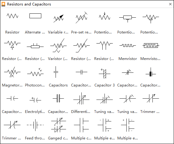
Resistors are crucial for dividing voltages, adjusting signal levels, reducing current flow, and biasing active elements. Types of resistors include:
- Variable Resistors
- Metal Film Resistors
- Metal Oxide Resistors
- Metal Strip Resistors
Variable Resistors
The main benefit of a variable resistor is that it allows the user to adjust the resistance as needed. Types include:
- Rheostat Resistor
- Digital Resistor
- Presets Resistor
- Potentiometer Resistor
Capacitors
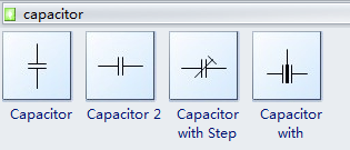
A capacitor's function is to store and release electrical energy within a circuit. Common types are:
- Ceramic capacitors
- Film and paper capacitors
- Aluminum, tantalum, and niobium capacitors
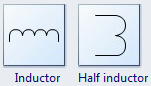
Inductors
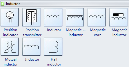
An inductor stores electrical energy as magnetic energy. Types of inductors include:
- Steel Core Inductor
- Solid Ferrite Cores
- Molded Inductors
- Ceramic Core Inductors
Diodes
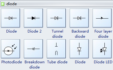
The above symbols represent diodes, which allow current to pass in only one direction while blocking it in the opposite direction. Types of diodes are:
- Light Emitting Diode (LED)
- Zener diode
- Photodiode
- PN junction diode
- Laser diode
Transistors
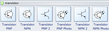
Transistors serve multiple functions, including controlling, amplifying, switching, and signal modulation. The main types of transistors are:
- Insulated-gate bipolar transistors (IGBTs)
- Field-effect transistors (FETs)
- Bipolar junction transistors (BJTs)
Logic Gates
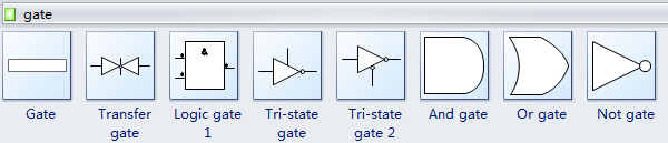
Logic gates perform logical operations on one or more binary inputs (0 and 1). For example, the AND gate multiplies two binary numbers, the OR gate adds them, and so on. Common types include:
- AND, OR, NOR, NOT, XOR, NAND, etc.
Amplifiers
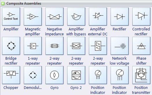
Amplifiers increase the strength of signals within a circuit. The types of amplifiers are:
- Audio Frequency Amplifier
- Intermediate Frequency Amplifier
- Ultrasonic Amplifier
- Operational Amplifier
Antennas
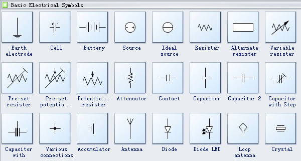
Antennas are used in wireless networks to receive and transmit signals from various wireless devices. Some common types include:
- Parabolic or dish antenna
- Grid antenna
- Sector antenna
- Patch antenna
Transformers
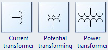
A transformer is an electronic component whose primary function is to transfer alternating current from one circuit to another by stepping the voltage up or down. Types of transformers include:
- Step-Up Transformer
- Step-Down Transformer
- Iron Core Transformer
Ammeter and Voltmeter
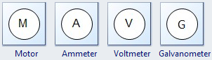
An ammeter is an electronic device that measures the current in a circuit. A voltmeter is a measuring device used to measure the potential difference (voltage) between two points in a circuit.
Types of ammeters include:
- Moving coil Ammeter
- Moving magnet Ammeter
- Digital Ammeter
Types of voltmeters include:
- Analog Voltmeters
- VTVMs and FET-VMs
- Digital Voltmeters
Miscellaneous Symbols
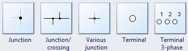
Connection Symbols
Source Symbols
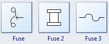
Fuse Symbols
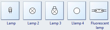
Lamp Symbols
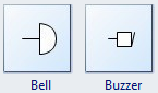
Bell and Buzzer
Inductor Symbols
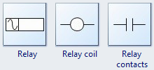
Relay Symbols
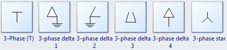
Phase Symbols
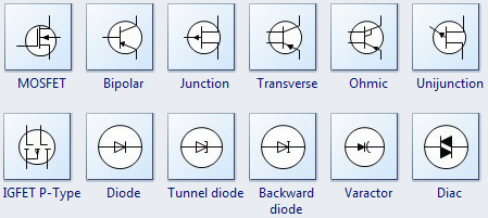
Semiconductor Symbols
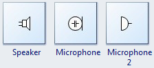
Speaker
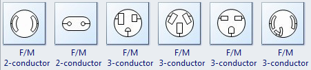
Conductor Symbols
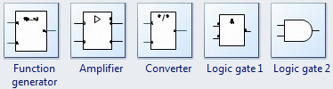
Integrated Circuit Symbols
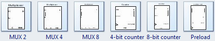
Digital Circuit Symbols
Create Circuit Diagrams with EdrawMax
Using the correct circuit symbols in the right places is critical. A single wrong symbol can disrupt your entire project, and fixing it often means rebuilding the entire circuit from scratch. This is why using reliable software like EdrawMax is highly recommended for creating circuit diagrams.
EdrawMax is a user-friendly software that is free for basic use. It offers hundreds of pre-generated libraries, providing you with all the electronic symbols you'll need. The software includes all the essential tools to help you create professional-quality diagrams efficiently. It is recommended by experts and can be used by anyone, regardless of their professional background.

More Related Topics


