Inverter Circuit Diagram: A Complete Guide
Your Comprehensive Resource for Inverter Circuit Diagrams
EdrawMax is an advanced all-in-one diagramming tool for creating professional flowcharts, org charts, mind maps, network diagrams, UML diagrams, floor plans, electrical diagrams, science illustrations, and more. Just try it, you will love it!
EdrawMax empowers software development teams to create asset mapping and models effortlessly. Experience it today!
An inverter is an electronic device that converts Direct Current (DC) into Alternating Current (AC). Alternating Current consistently changes its magnitude over time and periodically reverses direction. Direct Current is a unidirectional current that typically flows through a conductor, though it can sometimes flow through insulators.
Inverters perform the opposite function of converters. They do not generate power themselves; the DC source provides the power. While typically electronic, inverters can also be constructed using mechanical components. They are commonly used in applications involving high voltages and currents, with power efficiency often exceeding 95%. Power inverters are also employed in controlling the speed and torque of electric motors.
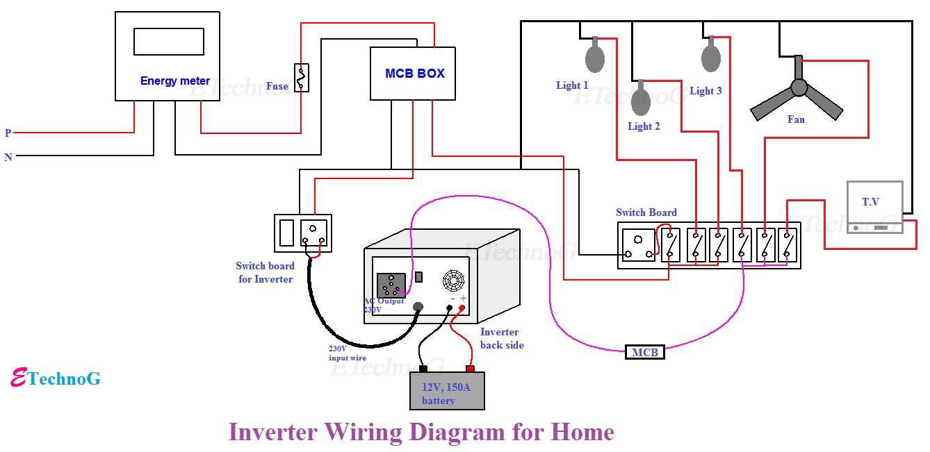
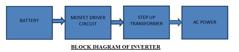
The inverter delivers 220V AC or 110V AC to connected devices through its output socket. When AC main supply is interrupted, inverter sensors detect this and route AC to the relay and battery charging section. From the relay, AC passes to the load, managed by line voltage. This line voltage is also directed to the battery charging section, where it's converted to direct current.
Understanding the main types of inverters is essential for proper selection and application.
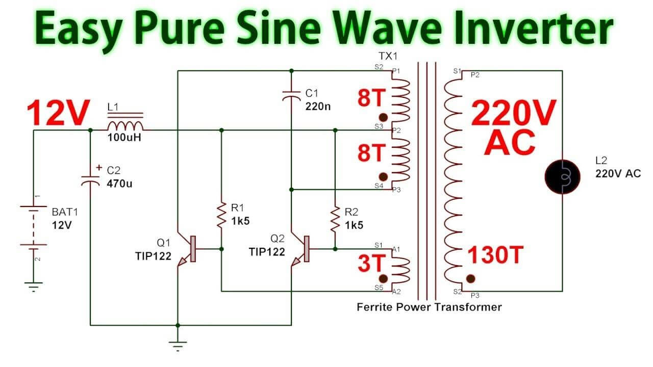
These fundamental inverters provide pure sine wave output without advanced features. They are ideal for sensitive home appliances including air conditioners, refrigerators, washing machines, computers, and televisions.
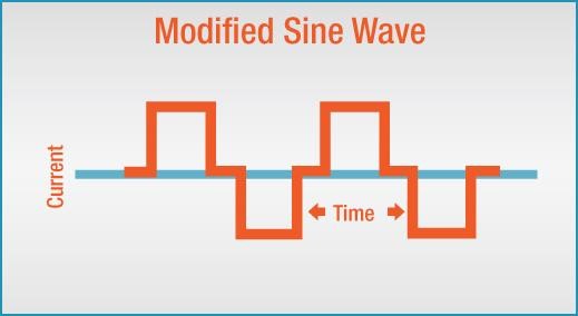
These cost-effective inverters produce a modified sine wave output suitable for less sensitive electrical devices like fans, bulbs, and microwave ovens. They typically convert 12-volt battery power and can be recharged using solar panel generators.
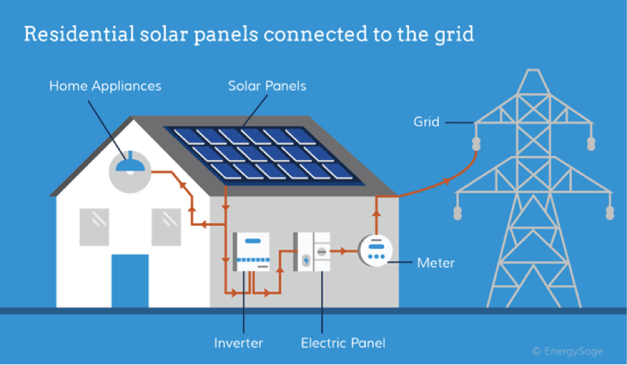
These advanced inverters utilize solar energy instead of traditional power sources to convert DC to AC, making them essential components in renewable energy systems.
Internally, inverters consist of switches, transformers, batteries, MOSFETs, and amplifiers. The DC stored in the battery is converted to AC through rapid switching operations. Switches continuously turn ON and OFF, while MOSFETs and transformers similarly switch DC voltage to create alternating voltage through electromagnetic induction.
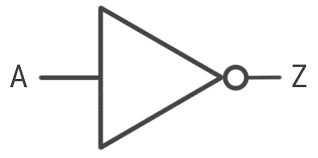
Before creating an inverter circuit diagram, understanding the logical symbol of a power inverter is essential. In electronics and logic design, the inverter is known as a NOT gate, performing logical negation by converting high signals to low and low signals to high.
Inverters are fundamental components in digital electronics, used extensively in state machines, decoders, multiplexers, and other logical circuits. When physical inverters are unavailable, they can be constructed using combinations of NAND and NOR gates.
The standard logic symbol for an inverter is illustrated below.
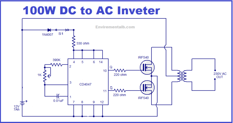
This section provides guidance for creating a simple 100-watt inverter circuit diagram. While commercial inverters are typically purchased, you can build one for project purposes by following these steps precisely.
Gather the following components to build your inverter:
The most efficient method for designing an inverter circuit diagram is using specialized computer software. EdrawMax provides comprehensive features for creating precise circuit diagrams, though other diagram-making software can also be utilized.
Inverters play a crucial role in modern energy management. Equipment utilizing inverter technology can reduce energy costs by up to 50% while operating more quietly and maintaining greater operational stability compared to non-inverter equipment.
Inverters effectively manage temperature variations in devices and can precisely calculate and respond to changing voltage and current requirements, ensuring optimal performance and protection.
Ready to create your professional inverter wiring diagram?
Follow our video tutorial and start designing today:


EdrawMax provides a reliable, user-friendly platform for creating professional circuit diagrams, including inverters. This comprehensive software includes all necessary features and libraries for effective diagram creation.
While basic diagram creation is free, advanced features require a subscription. The platform supports importing custom templates and offers numerous pre-generated templates. Additionally, EdrawMax enables project export in multiple file formats for maximum flexibility.