HVAC Symbols
Ready to Create Your HVAC Plan?
EdrawMax is the premier tool for diagramming and visualization. This comprehensive guide explains everything you need to know about **HVAC symbols** and **how to use them**. Get started for free today!
A **HVAC plan** visually details the layout and function of heating, ventilation, and air-conditioning units within a building. **HVAC symbols** are used to represent the various equipment and components in the plan. This guide will teach you about the different types and benefits of these symbols, how to find and use them, and the powerful features of EdrawMax for creating your own personalized HVAC designs.
1. What Are HVAC Symbols?
HVAC is an acronym for heating, ventilation, and air-conditioning. An **HVAC plan** is a schematic diagram that visually represents the structure and components of mechanical systems installed in buildings, houses, and other establishments for thermal comfort and improved air quality. **HVAC symbols** are used to depict the layout of devices, ventilation networks, and other components of an HVAC system. These systems are primarily used in corporate, residential, and industrial settings.
The **purpose of using HVAC symbols** is to design an accurate plan that satisfies environmental comfort requirements by adjusting air conditions. There are two common types of HVAC plans. A **central HVAC plan** is used when the system is located away from the residence or building, using delivery ductwork to distribute conditioned air. **Local HVAC systems** are typically placed near or within the conditioned zone, with minimal ductwork required.
Using HVAC symbols to create a plan offers various benefits before designing the mechanical system. A proper **HVAC plan** allows you to illustrate the size, position, and type of each component more efficiently, which can lead to lower electricity bills, better temperature regulation, and cleaner air. It can also enable remote access for system control.
HVAC symbols are standardized icons that represent the devices, ventilation network, and other components of a heating, ventilation, and air-conditioning system.
2. Types of HVAC Symbols
A wide variety of **HVAC symbols** are used to design schematic wiring and circuit diagrams that depict the layout and function of HVAC systems. The symbols you choose depend on the building's configuration and the project's specific requirements. Some universal symbols used in all HVAC plans include ducts, air filters, supply fans, and various electrical and control devices. We can categorize these symbols into four types based on their purpose and design. Here are the four main **types of HVAC symbols**:
2.1 HVAC Controls Symbols
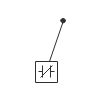
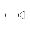
**HVAC control symbols** represent the components and devices that manage the heating, ventilation, and air-conditioning mechanisms, including power connections and regulators. These symbols are used to show gas and water pressure or to represent variable controls for adjusting motor speed and torque. Many are used in circuit diagrams to depict the control of fluid flow and the electrical modules that operate the system. Common HVAC control symbols include:
- **Temperature**: Indicates the temperature of the system or room.
- **Humidity**: Represents a device for measuring humidity.
- **Pressure**: Measures and displays the current pressure within the system.
- **Voltage**: Measures the voltage in the system.
- **Current**: Measures the electrical current in the system.
- **Timer**: Used to indicate a timed function or countdown.


Source: EdrawMax
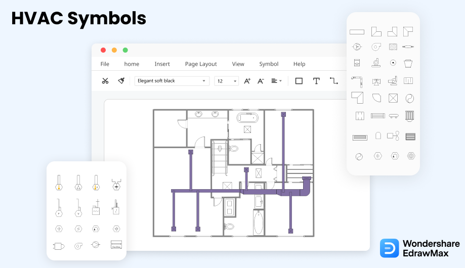
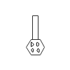
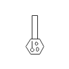
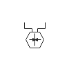
2.2 HVAC Equipment Symbols
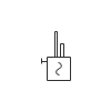
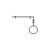
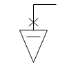
**HVAC equipment symbols** represent the electrical products, devices, and machinery used in an HVAC system. These symbols are essential for visually representing all major and minor components in an HVAC plan. The equipment can range from common devices like fans and air filters to larger external units like DX units and driers. Understanding these symbols is crucial for creating an accurate and effective HVAC plan. Common HVAC equipment symbols include:
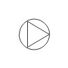
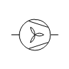
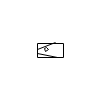
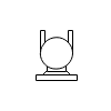
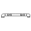
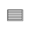
- **Fan blades**: Typically placed where a fan or exhaust will be located in the HVAC plan.
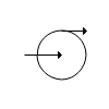
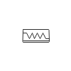
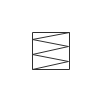
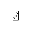
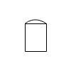
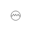
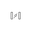
- **Silencer**: A device used to reduce noise from the motor or system.
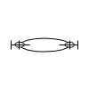
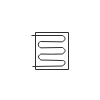
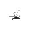
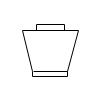
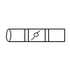
- **Condenser**: A critical heat transfer component that condenses vapor into a liquid.
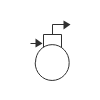
- **Drier**: An essential heat transfer component that condenses vapor into liquid.
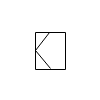
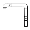
- **Muffler**: An advanced form of a silencer used to inhibit noise.
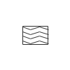
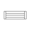
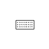
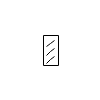
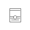
- **Filter**: A porous device that removes impurities or solid particles from a gas or liquid.


Source: EdrawMax
You May Also Like
Elevation Symbols
Article
Wardrobe Floor Plan Symbols
Article
LDAP Icons & Symbols
Article
Reflected Ceiling Plan Symbol
Article
Security Plan Symbols
Article
Table & Chair Symbols
Article


